Author Topic: Load Matching  (Read 7897 times)

0 Members and 1 Guest are viewing this topic.

Flux

  • Super Hero Member Plus
  • *******
  • Posts: 6275
Load Matching
« on: October 01, 2006, 05:28:54 PM »
Just a bit of an update.


Some time ago I posted a circuit using the alternator winding inductance as part of a boost converter. At that time I suspected that airgap alternators did not have enough inductance to make this work.


I was wrong and they do have enough to make it work at a few kHz. This method does have one advantage over the scheme I showed before, the diode drop is inside the boost voltage and has less effect.


This is the basic scheme.
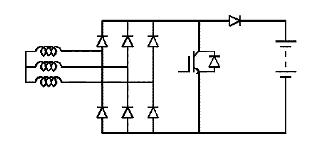


The active thing is a mosfet, sorry for the IGBT symbol but is easier to draw.


The series diode drop can be got rid of by using 3 mosfets in the bridge.
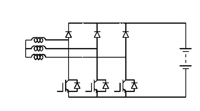


The 3 mosfet gates are driven together.


I tried this at about 5kHz and it works quite well. The machine squeals and it is fairlylikely that there is losses induced into the magnets but efficiency is quite good.


Having perhaps 100yds of cables radiating is not a particulary nice concept but would not matter if you have no near neighbours and don't listen to medium wave radio.


I wasn't prepared to persue things in this form so I looked at filtering the leads at the converter and adding small ferrite inductors, the inductance required at 30kHz is tiny, 200uH or so. The inductors can be a few turns round ferrite cores and cost little and can be made to cause negligible loss.


This is the set up.
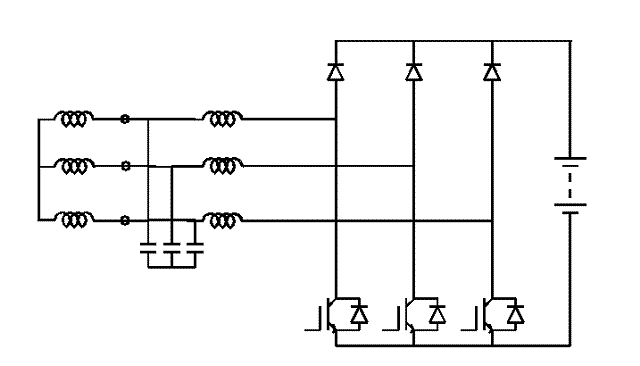


Filter capacitors are about 10uF motor run capacitors.


This is about as simple as it comes. A pwm driver with current feedback is used to control mosfet gates.


I did this some time ago and more things need investigating but I haven't got round to it.


The diodes need to be fast. Normal fast diodes seem to have a very high volt drop but come in sensible packages.


Ultrafast diodes are better and for the 24v case you are still within the range of schottky. The thing that I don't like is the fact that these animals come in very uninspiring packages mainly TO220.


There is no problem within the range where boost is taking place but in higher winds the full machine current uses this bridge, mosfets using their body diode.


Up to about 40A this looks to be possible but I would be reluctant to take it much higher.


Decent package mosfets and schottkys come at a stupid price.


I have thought of ways to transfer part of the current to a robust diode bridge when out of boost but I haven't tried it.


I will leave it with you for now to think about until I have checked a few more things.

Flux

« Last Edit: October 01, 2006, 05:28:54 PM by (unknown) »

stephent

  • Sr. Member
  • ****
  • Posts: 268
Re: Load Matching
« Reply #1 on: October 01, 2006, 03:11:34 PM »
Flux..

Won't "ringing" the coils with a chopper (so to speak) make them have a much higher currant peak then normal?

Especially near normal cut in?

And slapping more/less square wave demand across the same genny coils raise hob with the normal ebb and flow of the, again,  more/less sine wave pattern?

Looks like it may produce a bit of growl in the genny too, if using the coils for the inductance.

But the caps may have an additional bonux if designed just right outside of helping with the growl/load seen by the genny (and filtering)--capacitor improvement for the power factor. But then again--the PF is all over the place anyway using wind for the driver source.


I am really interested in a boost conveter for my wind gennys--much of the summer they sit turning just under cutin and not doing much good. Outside of the occasional thunderstorm that really tests the diode ratings, on the small one. And if it's just wearing out when it could contribute "something"--it's wasted effort on my part.

I have a rough draft of the main power handling circuit made with your "cutin bypass" type design and am working on the feedback/monitoring now.

It'll use a simple PicAxe 08M controller and have built-in dump load capabilities.

I just wish most of the wind gennys were "typical" instead of each installation being so $%%$ independant/different on the power profile, easier circuit design when one size fits all/most. OOOHHHH Wellllll..

« Last Edit: October 01, 2006, 03:11:34 PM by stephent »

SamoaPower

  • Sr. Member
  • ****
  • Posts: 417
Re: Load Matching
« Reply #2 on: October 01, 2006, 06:07:32 PM »
Bravo, Flux! Good to see more work being done on this.


I think you could improve on the losses by replacing the diodes with FET switches also, driven synchronously with the others but out of phase. May need some dead time.


I'm a bit confused since you say you tested at 5kHz, but when talking about the filter inductors, you mention 30kHz.


I think that, perhaps, the addition of the capacitors will somewhat negate the stator inductance and the boost is happening from the added inductors. If around 200uH, they should be well above minimum to keep them in continous mode at 30kHz. Of course, they would be subjected to core loss and saturation issues. I still want to try large air-core inductors here.


Have you looked at any waveforms yet?


I'm sure you're aware that twisting the transmission lines will tend to minimize radiation.


Combining functions of rectifiers and boost converter is a real boon.


I'm VERY interested in further developments.

« Last Edit: October 01, 2006, 06:07:32 PM by SamoaPower »

Flux

  • Super Hero Member Plus
  • *******
  • Posts: 6275
Re: Load Matching
« Reply #3 on: October 02, 2006, 02:01:58 AM »
Sorry I should have made the frequency thing clear.


I did the original tests at 5k, the alternator squealed so there is significant HF field induced in the surface(most likely plating) of the magnets. It will work well enough in that mode if you don't mind the noise. I pushed the frequency up and it still worked without the noise but it was messing up my frequency measuring equipment and it seemed unreasonable to pursue things in this form. The RF radiation would not be acceptable for a lot of people.


Having seen advantages from the inductors before the bridge, I decided to ignore the alternator inductance, add the filters and add ferrite inductors to replace the winding inductance. This removes any possible surface induced loss in the magnets and keeps the feed cables clean.


I used about 30kHz as a compromise between inductor size, filter efficiency and the layout problems.


If anyone wants to try it in the basic form I think at 5kHz it may be possible with standard diodes but the fets will need a good voltage rating or snubbers.


You can almost certainly get away with air cored inductors if you find they have some virtue that I don't follow. If you seriously reduce the inductor size things changes as you go into discontinuous conduction.


The thing changes to a form of high quality boost rectifier and the discontinuous chopped lumps of current more or less follow the input voltage waveform. The dc current becomes much less distorted. I had hoped that this would benefit alternator efficiency as they really don't like rectifier loads. In fact I saw no improvement in overall efficiency and didn't chase this mode. The inductance with the yoke removed from my cores may have been about 50uH.


If you are stuck with 12v then synchronus rectification may be justified. I tried the scheme at 12v and it was efficient enough to be usable but at 24v the efficiency is good enough not to add this complexity.


To Stephent

Capacitors can have a significant effect across the output of a motor conversion, where it influences the armature reaction and the leakage reactance and is often beneficial to output, especially series capacitors.


With air gap machines,both armature reaction and leakage reactance are very low and capacitors have negligible effect. It was this very low leakage reactance that made me think that the scheme might not work with air gap machines. Normally it is leakage reactance that is the important factor. For this boost it seems as though winding inductance is the factor, not the leakage component.


The peak current is not an issue as the boost is at low power when the alternator is producing a fraction of its full output. It does growl (at 5k more of a squeal).

Flux

« Last Edit: October 02, 2006, 02:01:58 AM by Flux »

dinges

  • Hero Member
  • *****
  • Posts: 1294
  • Country: nl
Re: Load Matching
« Reply #4 on: October 02, 2006, 03:49:03 AM »
Interesting idea.


Don't have enough knowledge/experience to be able to comment on it more in detail.


However, one thing. You know that the fast turning on/off of power to/from the windings puts an extra strain on the coils? It's the reason that induction motors that are to be used with a Variable Frequency Drive (frequency control) use wire with extra strong insulation. These motors are also known as 'inverter rated', IIRC. Normal motors are intended to be used with sinusoid-AC, which is much more 'gentle' to the motorwindings.


Using this scheme with coils that use a low insulation rating could lead to problems, over time.


Just a thought I had whilst reading about your idea.

« Last Edit: October 02, 2006, 03:49:03 AM by dinges »
“Research is what I'm doing when I don't know what I'm doing.” (W. von Braun)

willib

  • SuperHero Member
  • ******
  • Posts: 2414
  • Country: us
Re: Load Matching
« Reply #5 on: October 02, 2006, 08:58:51 AM »
flux i dont see it..

in all but the first example ,

the current in the fets is not going from  drain to source ?

sorry to through a monkey wrench in the works , but ...

if i'm wrong , i apologize in advance
« Last Edit: October 02, 2006, 08:58:51 AM by willib »
Carpe Ventum (Seize the Wind)

Flux

  • Super Hero Member Plus
  • *******
  • Posts: 6275
Re: Load Matching
« Reply #6 on: October 02, 2006, 09:38:16 AM »
In boost mode the volts are not high enough for the bridge diodes to conduct to battery. You have three wires with voltages on them at any instant and you short the lot together with fets. The positive ones will conduct in the conventional way. Those negative would conduct via the body diode but as all fets are gated they will actually conduct through the fet in the third quadrant. When you remove gate signal the conduction to the battery is via at least one bridge diode and a mosfet body diode.


You can amuse yourself for some time sorting out the various conduction paths but it really is nothing more than a modified  boost converter.

Flux

« Last Edit: October 02, 2006, 09:38:16 AM by Flux »

SamoaPower

  • Sr. Member
  • ****
  • Posts: 417
Re: Load Matching
« Reply #7 on: October 06, 2006, 10:44:13 AM »
Flux,


"You can almost certainly get away with air cored inductors if you find they have some virtue that I don't follow. If you seriously reduce the inductor size things changes as you go into discontinuous conduction."


The thought behind use of air core inductors is two fold. One, to eliminate core loss and saturation issues at high current levels and second, the lack of suitable cores in my junk box.


I'm not thrilled by the idea of having to wind #4 or #6 around cores to get the resistance down.


As I see it, the main benefit in using ferrite is to reduce the physical size. If size isn't an issue, 3-4" diameter air core inductors are easy. I'm still not sure about the trade-off of increased wire length for a given inductance and resistance.


Any thoughts?

« Last Edit: October 06, 2006, 10:44:13 AM by SamoaPower »

Flux

  • Super Hero Member Plus
  • *******
  • Posts: 6275
Re: Load Matching
« Reply #8 on: October 07, 2006, 01:08:51 AM »
You will almost certainly get a higher Q with ferrite cores, but for the inductance values needed air core most likely will be good enough.


Not having ferrites is the best argument against them. Core loss will be very small.


Saturation is not really an issue at higher current levels as the fets will not be chopping except at low current in the boost mode.


Wire should be litz or multi stranded and will be no problem to wind. Even with air cored coils you should be thinking about litz. Harmonics of the chop frequency will be up in the low RF range and eddy loss and skin effect in solid wire will make the coils poor ( may still be good enough, I don't think it is very demanding).


Tape wound copper coils may be good enough if the tape is fairly thin.

Flux

« Last Edit: October 07, 2006, 01:08:51 AM by Flux »

elt

  • Sr. Member
  • ****
  • Posts: 328
Re: Load Matching
« Reply #9 on: October 07, 2006, 02:45:45 PM »
Not being an analog guy, I've had to search the web for some ideas on inductor parameters; I found what I think are two nice resources:


The first suggests inductor parameters for DC-DC converters -

http://www.coilcraft.com/apps/selector/selector_1.cfm


The second is an air core inductor simulator -

http://www.oz.net/~coilgun/mark2/inductorsim.htm


For the small boost circuit I'm trying make (about 200 watts), the coilcraft page suggest anywhere from a 68uh to 200uh+ depending on the current ripple.


The air core inductor simulator seems to be in the ballpark with some real world coils that I've been able to measure...


I have a question though; what should the output voltage be? "24 volts" is used generically, but wouldn't 29 or 30 volts be more likely to be above battery voltage? Being a digital guy, I'll use an 8 pin microcontroller for the pwm generator. Besides the pwm generators, it (attiny45) has four analog to digital converters so it could read the battery voltage and boost the input to that (or a little more) if matching the voltage on the fly makes sense... otherwise, if it's going to boost to a fixed voltage, what should that be?


Thanks,

 - Ed.

« Last Edit: October 07, 2006, 02:45:45 PM by elt »

SamoaPower

  • Sr. Member
  • ****
  • Posts: 417
Re: Load Matching
« Reply #10 on: October 08, 2006, 12:28:33 AM »
I'm guessing (don't know exact cut-in yet) that boost currents of 30-40 Amps may be necessary for my machine. At these levels the AC flux density in the core may be significant. It's not an easy calculation with the PWM frequency superimposed on the alternator frequency and both components contributing to core loss and  temperature rise, which may be the more significant issue.


With energy storage levels of around one millijoule needed, cores would need to be of pretty good size for this and to handle wire(s) large enough to achieve reasonable I^2R losses.


Usually, harmonic consideration up to the 5th or 7th is sufficient which would mean about 200kHz (for 30kHz PWM). Yes, skin effect is starting to become an issue. I would probably use 8-in-hand #14 (#5 equiv.). Litz? I like it but can't afford it.


"Saturation is not really an issue at higher current levels as the fets will not be chopping except at low current in the boost mode."


Well, I guess I didn't really think of 30-40 Amps as "low current".


Thanks for the input.

« Last Edit: October 08, 2006, 12:28:33 AM by SamoaPower »

Flux

  • Super Hero Member Plus
  • *******
  • Posts: 6275
Re: Load Matching
« Reply #11 on: October 08, 2006, 02:44:19 AM »
Ed  I am not sure what your boost converter is for. If it is for the scheme proposed here you can ignore output voltage.


Your gate drive needs to be arranged so that the blade speed increases with wind speed to keep the prop on the peak of its power curve.


Output volts will be clamped to battery volts, you need to control pulse width to match prop speed.


I have absolutely no idea how you do it digitally, you may need a speed signal.


I use battery current as the control signal and make the gain of the system about right to get the alternator characteristic ( similar to a compound wound generator with differential compounding). If you use constant gate pulse width the thing will stall.

Flux

« Last Edit: October 08, 2006, 02:44:19 AM by Flux »

elt

  • Sr. Member
  • ****
  • Posts: 328
Re: Load Matching
« Reply #12 on: October 08, 2006, 04:26:36 PM »
Hi Flux,


I think that I don't have a complete view of "the big picture."


You wrote "gate drive needs to be arranged so that the blade speed increases with wind speed to keep the prop on the peak of its power curve."


I thought that you kept the blade out of stall by choosing a higher cut-in speed and then used the booster to reclaim power from the lower voltages.


While I understand that the battery will clamp the output voltage of the booster circuit, are you saying that you keep boosting (running the PWM) even after the alternator would be generating battery voltage on its own?


Thanks again,

 - Ed.

« Last Edit: October 08, 2006, 04:26:36 PM by elt »

Flux

  • Super Hero Member Plus
  • *******
  • Posts: 6275
Re: Load Matching
« Reply #13 on: October 09, 2006, 02:00:01 AM »
I have found some test results that may help to explain things a little better.The first is a test on the alternator directly at 24v


The next is the same alternator into 12v.


The final one is the complete scheme.


You need to imagine that the direct connection at 24v is about right above 14 mph.


It will likely cut in about 10 mph with the prop running very fast but will not be very good below 12 mph.


The second curve is with the alternator loaded at 12v. You can regard this as being loaded at 24v via a fixed 2:1 boost converter. The cut in speed is halved so we should now start about 6 mph but the slope is far too high and by 10 mph the blades will be stalled.


By using current feedback to phase the gate pulses back the converter boosts from a progressively higher voltage as the prop sped increases, reducing the slope of the curve to match the prop. By about 14 mph the converter input volts will reach 24v and the main alternator will take over. Further increase in current will phase back the converter gate drive and finally it will stop.


The final curve has the low slope at low wind speed and high slope in high winds to keep the prop tracking the cube law power curve at the input of the alternator.


I hope this makes things clearer, I forgot that I had transfered this data from the old computer.

Flux

« Last Edit: October 09, 2006, 02:00:01 AM by Flux »

SamoaPower

  • Sr. Member
  • ****
  • Posts: 417
Re: Load Matching
« Reply #14 on: October 16, 2006, 04:30:47 PM »
Flux,

I'm curious about one of your comments.


"The dc current becomes much less distorted. I had hoped that this would benefit alternator efficiency as they really don't like rectifier loads. In fact I saw no improvement in overall efficiency and didn't chase this mode."


I would also think that an improvement in efficiency is possible using this scheme. I wonder why you, in fact, didn't see it.


If you're able to derive current from the portions of the input waveform that are below the main rectifier cut-in, it would seem that total output should increase.


Of course, the closed-loop bandwidth would have to accomodate the alternator frequency  to allow the PWM to follow the input waveform. Given the high ratio of PWM frequency to input frequency, this would not seem difficult.


Have you had any further thoughts about this aspect?

« Last Edit: October 16, 2006, 04:30:47 PM by SamoaPower »

Sly

  • Newbie
  • *
  • Posts: 44
Re: Load Matching
« Reply #15 on: November 28, 2008, 05:20:42 AM »
Hi Flux and all,


I was just curious if any of you has done additional testing on this set up?


Tks

Sly

« Last Edit: November 28, 2008, 05:20:42 AM by Sly »

Flux

  • Super Hero Member Plus
  • *******
  • Posts: 6275
Re: Load Matching
« Reply #16 on: December 03, 2008, 07:12:45 AM »
I haven't looked here for ages, I hadn't thought there would be any more comments.


I did get very good results with the boost circuit using mixed diodes and mosfets with the alternator inductance. I didn't like the idea of sending RF interference all over the place and I did try it with capacitors across the alternator windings and small ferrite inductors for the boosting. It seemed to work very well on bench test but it never got tried on a mill, I have a feeling that it is better than the early schemes with conventional boost converter. I saw no improvement making it work as a low distortion rectifier and thought it was better with the larger inductors.


Most of my recent experiments have been with a buck converter scheme and that has some advantages in that the diode losses and the winding and cable losses have far less effect. The tests on a 6ft machine have been very positive and if properly engineered this looks to be near perfection.


For home build the buck converter for a large machine would be a challenge and I suspect the average person would be well advised to stick to the boost arrangement especially for 24 or 48v. For 12v the voltages on a buck converter are not as challenging and 12v schemes don't really suit large machines so having the less diode and I^2R losses of the buck scheme may suit 12v better.


I still think there is some mileage in what I called hybrid schemes with a main winding using most of the space matching direct in high winds and a small higher voltage winding feeding a buck converter to deal with low winds and still contributing in high winds. It is probably very similar to the boost scheme using one winding in performance but may have the edge for 12v with the lower diode losses from bucking rather than boosting.


All these schemes are miles ahead of direct connection that everyone seems to accept and they are all better natured than star/ delta switching which is better than the standard method.


Flux

« Last Edit: December 03, 2008, 07:12:45 AM by Flux »

Sly

  • Newbie
  • *
  • Posts: 44
Re: Load Matching
« Reply #17 on: December 03, 2008, 05:18:59 PM »
Thanks Flux,


I will read this over and over to try and grasp all of it. Once this is done I will pick a path and go for it....because I like you, I'm not content with "just" direct connection.


Off topic: I have done some fine tuning of my tail and will see how the furling behaves in strong winds once we get them but I strongly suspect the offset will have to be increased.


I hope you never get tired of answering questions i.e. repeating yourself for us newbies...because we need all the help we can get...


I am working hard at understanding all of this it ain't easy. But considering I only discovered this site approx. 10 months ago and I already have a 10' footer flying makes me proud.


Just received the Dans new book, will read while sipping a beer over the Holidays!!


Once again thank you!!


sly

« Last Edit: December 03, 2008, 05:18:59 PM by Sly »

martin1

  • Newbie
  • *
  • Posts: 32
  • Country: se
Re: Load Matching
« Reply #18 on: December 03, 2008, 06:53:57 PM »
How much will the small winding contribute in high winds? Do you think it would be possible to skip the converter and just cut it out completely in high winds and compensating for the bigger gap with larger magnets.
« Last Edit: December 03, 2008, 06:53:57 PM by martin1 »

Sly

  • Newbie
  • *
  • Posts: 44
Re: Load Matching
« Reply #19 on: December 12, 2008, 04:47:38 PM »
Hi Flux,


I have read this over and over and other threads and I am confused i.e. it is preferable/possible to retain my main bridge rectifier and run the boost bridge in parallel. Is this feasible or does the regular bridge have to be removed?


Also with your permission I would like to utilize your PWM circuit you posted in a previous thread to Oztules in May 06. I will run it by somebody who knows what they are doing to adapt to 48V. (Unless you have already done this and are willing to help....as if you don't do enough of that already!!)


Your patience and help is greatly appreciated believe me I am not a free loader but it's just I have limited electronics knowledge.


Tks (once again)

sly

« Last Edit: December 12, 2008, 04:47:38 PM by Sly »