Author Topic: LED lighting driver circuit for remote system  (Read 12998 times)

0 Members and 1 Guest are viewing this topic.

richhagen

  • Hero Member
  • *****
  • Posts: 1597
  • Country: us
LED lighting driver circuit for remote system
« on: October 12, 2007, 06:22:56 PM »
Last April I went with BThumble to Vanua Balavu Fiji to help with a computer lab at a school there.  There is no power plant on that island, although there are a few generators and some small solar power systems in use.  We had taken some flourescent lights with us to use with the small solar lighting systems that BT had designed for some of the houses there.  Some of them were "trouble lights" of the automotive variety, and some were compact flourescents that Commanda had contributed.  As BT put it, the trouble lights lived up to there name, they had a single transistor driver circuit that burned out in short order for all of them.  We had also taken some LED lights, which while robust were not likely as efficient as a flourescent.  So far as I am aware, the compact flourescents worked out OK.

You can read about that trip here:

http://www.fieldlines.com/story/2007/6/5/85322/76409

or at www.smallsolar.org


In the quest for a better solution to this problem, I have been experimenting with a newer more efficient generation of LED's.  First, I obtained some MR16 type bulbs commonly used in track lighting:


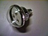
These have a driver built in to limit the current, and have 3 Cree LED's claiming 80 lumens per watt.  I was happy with the amount of light that they output at just under 3 volts from my 12V system and have been lighting up a laundry room for a few months now without incident.  On the down side is that they are rediculously expensive, so buying a large quantity would be more difficult.  


I wound up having 30 boards made up with 3 of the CREE LED's. The LED's were from a bin ranging from about 80 to 87 lumens per watt.  The price nearly doubles for the next bin up from there, so for now these will have to do.  


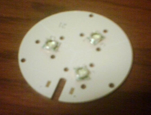
These boards are aluminum with the circuit laminated to them, which should aid in heatsinking and cooling I hope. The boards are similar to, but larger than the boards in the MR16 bulb, and the three Cree LED's are connected in series.  I will of course have to come up with a driver circuit for these boards, and hence the purpose of this post.  I was hoping for something simple, reasonably efficient, and very reliable.  


I am not an electronics guru.  I read up on Commanda's posts regarding LED drivers here:

http://www.fieldlines.com/story/2007/4/20/95351/1614

http://www.fieldlines.com/story/2007/4/26/82929/6080

http://www.fieldlines.com/story/2007/5/1/74856/25992

I decided to copy her circuit 4 and attempt to adapt her "Circuit 4" for my situation.  I have linked to her sketch here for reference:


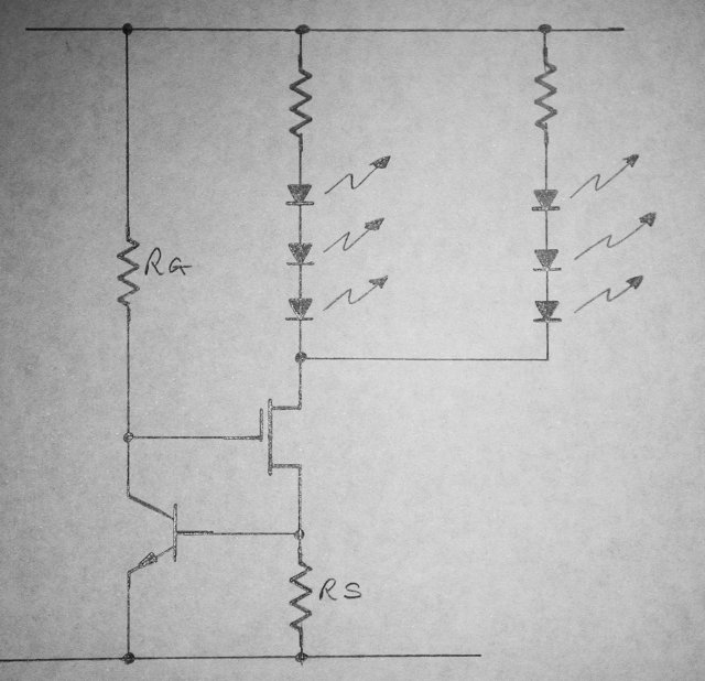
For a test power supply I used 9V batteries in series so that I could pull 9, 18, and 27 volts.  For the NPN transistor, I happened to have a few 2N3904's in my box, and for the FET, I had a few 75339P N-chanel mosfets as well.  I breadboarded the circuit with 100 ohm LED's for Rg and Rs, since I was powering only one string, I did not use an equalizing resistor.


I found that I got about 11ma through the circuit.  I proceeded to reduce the value of Rs, and somwhere along the line I noticed that Rg was getting quite warm (smoke).  Upon experimenting with that I ended up increasing that value all the way to 10K ohms, and a little more experimenting would be useful to optimize that resistor value.  Now, unlike normal LED's, I am trying to drive a steady 350ma through these.  As I reduced the values for Rs, I noticed that the 9V tap never rose above about 60ma.  


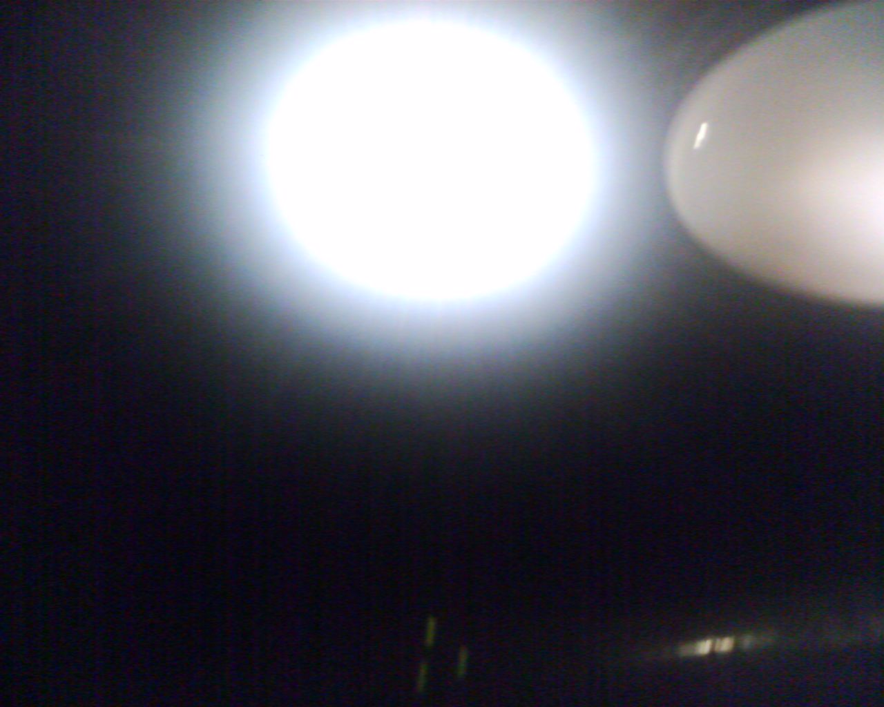
I also found that I did not have a sufficiently small resistor in my box for the value of Rg.  I wound up paralleling several 10 ohm and 15 Ohm resistors.  I wound up with 3 @ 10 Ohm, 3 @ 15 Ohm, and one at 56 Ohm, all in parallel.  This yielded good results.  The circuit drew approximately 345 ma from the 18 and 27 volt taps.  The value reduced to the 330's at 27V as the FET got rather hot rather quickly without a heat sink.  The LED's were blindingly bright, although I had no way to quantitatively measure the output.  


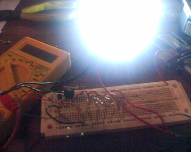
My math puts the value of an equivelant resistor for the ones I had in parallel at 1.93 Ohms or so, so I will probably try to get a few around that value that can handle the current and go from there.  With only four components, these drivers should be relatively easy to fabricate.  


I am planning to put three or four boards, each board with its own driver, into one fixture to make room lights.  That way, if one driver, or one board fails, there will also be a bit of redundancy.  


Absent any improvments gleened from here, my next step will be to make a few prototype board and a sample fixture for a longer term test here.


Suggestions welcomed, Rich

« Last Edit: October 12, 2007, 06:22:56 PM by (unknown) »
A Joule saved is a Joule made!

richhagen

  • Hero Member
  • *****
  • Posts: 1597
  • Country: us
Re: LED lighting driver circuit for remote system
« Reply #1 on: October 12, 2007, 12:27:34 PM »
Already I noticed a typo.  The part about not having a sufficiently small resistor is refering to Rs, not Rg, once I put in the 10K resistor for Rg, I left that one alone.  Rich
« Last Edit: October 12, 2007, 12:27:34 PM by richhagen »
A Joule saved is a Joule made!

wooferhound

  • SuperHero Member
  • ******
  • Posts: 2288
  • Country: us
  • Huntsville Alabama U.S.A.
    • Woofer Hound Sound & Lighting Rentals
Re: LED lighting driver circuit for remote system
« Reply #2 on: October 12, 2007, 02:53:00 PM »
Also check out this premade LED Circuit Board

http://www.fieldlines.com/story/2005/3/12/41720/1212

« Last Edit: October 12, 2007, 02:53:00 PM by wooferhound »

commanda

  • Hero Member
  • *****
  • Posts: 731
Re: LED lighting driver circuit for remote system
« Reply #3 on: October 12, 2007, 06:12:50 PM »
Rg only has to supply gate leakage current to the fet, and enough current so the bipolar transistor has some small amount of collector current to work with. On a 24 volt supply, I was using 1 M.


Rs can be calculated using ohms law. Vbe of the npn bipolar transistor divided by the drain current of the fet. Because the bipolar is operating right at the knee of its Vbe curve, this voltage will typically be closer to 0.5 volts rather than the 0.6 volts typically quoted for a bipolar transistor.


So, for 350ma, Rs becomes 0.5/0.35 = 1.43 ohms. Power dissipation will be I * I * R = 0.175 watts (negligible). 1.5 ohms is the nearest preferred value.


Amanda

« Last Edit: October 12, 2007, 06:12:50 PM by commanda »

ghurd

  • Super Hero Member Plus
  • *******
  • Posts: 8059
Re: LED lighting driver circuit for remote system
« Reply #4 on: October 12, 2007, 06:30:48 PM »
Looks great!


Nice to see someone doing the high-tech circuits.

G-

« Last Edit: October 12, 2007, 06:30:48 PM by ghurd »
www.ghurd.info<<<-----Information on my Controller

richhagen

  • Hero Member
  • *****
  • Posts: 1597
  • Country: us
Re: LED lighting driver circuit for remote system
« Reply #5 on: October 12, 2007, 06:39:25 PM »
Thanks for that, I will increase Rg and decrease Rs and give it a go.  Rich
« Last Edit: October 12, 2007, 06:39:25 PM by richhagen »
A Joule saved is a Joule made!

richhagen

  • Hero Member
  • *****
  • Posts: 1597
  • Country: us
Re: LED lighting driver circuit for remote system
« Reply #6 on: October 12, 2007, 06:41:36 PM »
I don't know about high tech, at least on my part.  Maybe Amanda's and Cree's.  I used Amanda's circuit, I only copied it and changed a few values, and I ordered the LED's and boards via the manufacturer.  My part of it is decidedly low tech assembly.  Rich
« Last Edit: October 12, 2007, 06:41:36 PM by richhagen »
A Joule saved is a Joule made!

richhagen

  • Hero Member
  • *****
  • Posts: 1597
  • Country: us
Re: LED lighting driver circuit for remote system
« Reply #7 on: October 12, 2007, 06:51:07 PM »
Hi Woofer, I had seen that one, it is a nice board, but it is resistance controlled, like circuits I have built in the past, which has the drawback on a variable voltage system of either wasting a bit of power with fewer LED's and more resistance in series, or having variable light output with more LED's in series and less resistance.  I think Amanda's circuit will be relatively efficient and give a basically steady light output.  I know someone is going to say that PWM would be more efficient with the voltage swings of the solar battery power system, and would give a steady light output, - and it would - but remember that it has to be reliable over the long term, I have to actually be able to assemble it, and I likely don't have much in the way of the parts on hand.  My supplies of 'obsoletium' and 'unobtainium' are running low although I do have access to 'EBAYnium'.  :-) Rich
« Last Edit: October 12, 2007, 06:51:07 PM by richhagen »
A Joule saved is a Joule made!

commanda

  • Hero Member
  • *****
  • Posts: 731
Re: LED lighting driver circuit for remote system
« Reply #8 on: October 12, 2007, 08:17:47 PM »
Nice to see someone doing the high-tech circuits.


You haven't seen the night-light version yet. Must build it properly and publish it soon.


Amanda

« Last Edit: October 12, 2007, 08:17:47 PM by commanda »

ghurd

  • Super Hero Member Plus
  • *******
  • Posts: 8059
Re: LED lighting driver circuit for remote system
« Reply #9 on: October 12, 2007, 08:59:32 PM »
You have my complete and undivided attention!


(nice to see you are back more often)

G-

« Last Edit: October 12, 2007, 08:59:32 PM by ghurd »
www.ghurd.info<<<-----Information on my Controller

richhagen

  • Hero Member
  • *****
  • Posts: 1597
  • Country: us
Re: LED lighting driver circuit for remote system
« Reply #10 on: October 13, 2007, 12:06:34 AM »
Ok, I tried Rg at 1 MOhm, I got eradic results on the lower voltages.  It seemed to work fine with a 470 KOhm resistor and the current across it should still be essentially negligible. I am planning this for a 12V battery circuit charged by a solar panel, but want it to survive if they connect it across a solar panel with no battery. This was done with laptops and a wind turbine in Fiji with apparently somewhat smokey results.  I figure the battery may need replacing first, and in spite of the best efforts users may get a little creative with how it is connected.  


Empirically, I'm still coming in a bit higher at about 1.7 Ohms for my 350ma, of course with the margin of error in the resistors, it could easily shift about a bit.  These LED's can be driven at a higher current with proper heat sinking, but their efficiency goes down, their lumen/Watt rating is at 350mA.  I will order up some 1.5 Ohm resistors and then stick with the 470K for Rg, using the 3904 NPN's and the 75339P FET's that I have.  I will plan to connect the NPN and the FET to the same heat sink when I plan the tiny board so any heat from the FET will effect the NPN.  Rich

« Last Edit: October 13, 2007, 12:06:34 AM by richhagen »
A Joule saved is a Joule made!

scottsAI

  • Hero Member
  • *****
  • Posts: 884
Re: LED lighting driver circuit for remote system
« Reply #11 on: October 13, 2007, 01:54:41 PM »
Hello richhagen,


  1. w LED have a forward voltage of 3.3v at 300ma = 1w. (from Cree 1w LED Data Sheet)
  2. stacked will require 10v to work correctly at 300ma. (350ma is max rating, should back it off)


(LED will light with 2.6v low current, plot of current and forward voltage on data sheet.)

Check each manufactures data sheet, I have seen numbers below 3v and near 4v at LED rated output.


Using series resistance to control the power to the LED is a serious waste of power.

With 18v driving the 10v LED string, 2.4 watts is wasted, 3/(3+2.4) = 55.6% efficient. Not good.


Place all the LED in series and boost the voltage with current control to control the brightness.

(all depends on how many LEDs and supply voltage, may need to buck the voltage)

Will require a switching regulator IC and inductor, not much more costly than the components your using (except yours were free:-) The switcher should get you down below half watt loss.

Considering the cost of the LEDs, the switcher and inductor will be cheap.


Have fun,

Scott.

« Last Edit: October 13, 2007, 01:54:41 PM by scottsAI »

richhagen

  • Hero Member
  • *****
  • Posts: 1597
  • Country: us
Re: LED lighting driver circuit for remote system
« Reply #12 on: October 16, 2007, 01:03:42 AM »
This is to run off of a 12 volt battery system, the maximum number I can put in series for it to output much light when the battery is low is 3.  I only tested it on higher voltages to make sure it won't blow up.  I don't expect it to ever see more than 16 Volts in normal operation, unless someone connects it to a panel without a battery, and that would only be about 21 volts or so max.  I just want it to have a chance of surviving the minor mishaps that untrained people may cause by fiddling with it.  


The datasheet for the LED's is here:

http://www.cree.com/products/pdf/XLamp7090XR-E.pdf


They have a forward current rating of 1 Amp maximum with proper heat sinking, they are from the P4 Bin and are rated to be 80.6 to 87.4 lumens per Watt at 350 mA. At 350mA they should have a voltage across them of about 3.3 volts or so.  Under normal operation I should loose about 2 volts or 18% of my power through resistance, mostly in the FET.  At 12 Volts and 350mA, if the LED's are performing to specification at about the middle of the bin I should see in the range of 59 Lumens per Watt in the finished circuit, which, although not quite what a new flourescent will put out, is not that bad considering the reliability it should achieve.  


I am not an electronics whiz like some of the folks here.  Amandas circuit seemed like a reliable circuit that would put out steady light, and could survive a bit of abuse.  I am aware that a buck boost converter to hold the power right at an ideal point for the LED's would be more efficient, but I don't know how to build or assemble a reliable circuit to do that at this point.  It seems hard to beat 4 components, 2 resistors, a transistor and a FET for simplicity.  If there are more components, there is more stuff to break.  Where these are going, there will be no one to fix it and no easy way to replace it when it fails. I plan to put 3 or four independent drivers and LED strings in each fixture, that way if one fails to open circuit, the light will still work, just with diminished output.  


Just trying to make them work - Rich

« Last Edit: October 16, 2007, 01:03:42 AM by richhagen »
A Joule saved is a Joule made!

richhagen

  • Hero Member
  • *****
  • Posts: 1597
  • Country: us
Re: LED lighting driver circuit for remote system
« Reply #13 on: October 17, 2007, 12:42:18 PM »
I just checked a compact flourescen lighting package.  They are 13 Watts and output 825 Lumens, or about 63 Lumens a Watt according to their specifications.  They claim this is the equivelant of a 60 Watt incandescent, which would be about 13.75 Lumens a Watt then.  


I don't feel that bad about the results then.  I will be within 10% of the output per watt most of the time when the battery is not charging and is lower.  If it is run in the day, the efficiency would be a bit lower due to the higher voltage of the battery while charging, but hopefully light won't be needed then as it will be daytime.  -Rich

« Last Edit: October 17, 2007, 12:42:18 PM by richhagen »
A Joule saved is a Joule made!

ghurd

  • Super Hero Member Plus
  • *******
  • Posts: 8059
Re: LED lighting driver circuit for remote system
« Reply #14 on: October 17, 2007, 01:06:06 PM »
Might be able to add a circuit that would only allow the LEDs to be turned on if the PV was below (say) 12.0V.  Then they couldn't turn it on in the daytime, or leave it on 24/7.  

I might be able to think of a circuit capable of doing that, LOL.

G-
« Last Edit: October 17, 2007, 01:06:06 PM by ghurd »
www.ghurd.info<<<-----Information on my Controller

richhagen

  • Hero Member
  • *****
  • Posts: 1597
  • Country: us
Re: LED lighting driver circuit for remote system
« Reply #15 on: October 17, 2007, 09:15:27 PM »
There's an LV disconnect on the surplus charge controllers I have, but they are potted and I see no way to adjust it.  12V might be a little bit too low, a charged standing 12V battery will be above that.  Rich
« Last Edit: October 17, 2007, 09:15:27 PM by richhagen »
A Joule saved is a Joule made!

ghurd

  • Super Hero Member Plus
  • *******
  • Posts: 8059
Re: LED lighting driver circuit for remote system
« Reply #16 on: October 17, 2007, 09:36:35 PM »
I mean use the PV voltage to determine if it is daylight or dark.

It would not be related to the battery voltage. Usually.

Like a anti- dump controller, but before "the night time blocking diode".


If the sun is out, the PV will be above 12.0V, so the LEDs can't turn on.

If the sun is down, the PV will be below 12.0V regardless of if the battery is at 11.0V or 14.4V.


G-

« Last Edit: October 17, 2007, 09:36:35 PM by ghurd »
www.ghurd.info<<<-----Information on my Controller

richhagen

  • Hero Member
  • *****
  • Posts: 1597
  • Country: us
Re: LED lighting driver circuit for remote system
« Reply #17 on: October 18, 2007, 01:55:03 AM »
Oh, I see, the Trace C12 uses a similar means to turn lights on at dusk, but when the panel voltage drops below 3V.  Rich
« Last Edit: October 18, 2007, 01:55:03 AM by richhagen »
A Joule saved is a Joule made!

Joel

  • Newbie
  • *
  • Posts: 34
Re: LED lighting driver circuit for remote system
« Reply #18 on: October 19, 2007, 10:59:43 AM »
I may be of some help.  Here is a circuit I use for driving 3 Luxeon I LEDs in series.  Small component count and the chips can be bought in quantities of 25 for about $11 directly from OnSemi.


http://tutorials.boilingpondscemetery.com/LEDLighting/LuxeonDriver/default.aspx


Not sure how it would fare under-driving the LEDs though.  I use it for driving Luxeons off my landscape lighting transformer.  The schematics that OnSemi has provided have so far been right on.


I have some switching supply Maxim chips coming in that promise similar results without the heat build-up this driver produces with large voltage differences.


LED driver ICs have become plentiful and cheap.  Don't overlook them.


Joel

« Last Edit: October 19, 2007, 10:59:43 AM by Joel »

Joel

  • Newbie
  • *
  • Posts: 34
Re: LED lighting driver circuit for remote system
« Reply #19 on: October 19, 2007, 11:03:50 AM »
Sorry, should have specified that I am refering to the NUD4001 driver circuit, not the LM317.


Joel

« Last Edit: October 19, 2007, 11:03:50 AM by Joel »

Joel

  • Newbie
  • *
  • Posts: 34
Re: LED lighting driver circuit for remote system
« Reply #20 on: October 19, 2007, 12:45:30 PM »
And one more I'm looking into...


http://www.catsemi.com/products/CAT4201.asp


Joel

« Last Edit: October 19, 2007, 12:45:30 PM by Joel »

richhagen

  • Hero Member
  • *****
  • Posts: 1597
  • Country: us
Re: LED lighting driver circuit for remote system
« Reply #21 on: October 22, 2007, 03:26:40 PM »
Hi Joel, I actually did look at the catsemi chip.  My LED boards are wired 3 in series.  For that chip you need a minimum surplus of 3 volts in your power supply over what is drawn - so I don't think I can use that one for this application.  I will have to take a more detailed look at your other circuit as soon as I get a chance.  Thanks for your replies.  Rich
« Last Edit: October 22, 2007, 03:26:40 PM by richhagen »
A Joule saved is a Joule made!

Joel

  • Newbie
  • *
  • Posts: 34
Re: LED lighting driver circuit for remote system
« Reply #22 on: October 24, 2007, 12:10:58 PM »
NP.  Just got my samples from Maxim the other day.  TINY!  3mm x 3mm.  Guess it's time to play around with reflow soldering in the toaster-oven...  The specs look promising though.  Here's the app note from Maxim for doing almost exactly what you are looking to do including a board layout.  Eliminating the rectifier diodes will give better efficiency but will require the correct polarity.  Change the sense resistor to .57 ohms for a 350mA output.


http://www.maxim-ic.com/appnotes.cfm/appnote_number/4086/CMP/BTDT


Data sheet and link to design tool can be found here:

http://datasheets.maxim-ic.com/en/ds/MAX16819-MAX16820.pdf


Also, for cheaper premade LED lamps (standard edison base and bi-pin base) check out http://www.kaidomain.com/WEBUI/SubCategory.aspx?TranID=8218&Name=LEDs


I have some things on order from them so not overly sure how good the products are as of yet.  Email replies are slow though.


Joel

« Last Edit: October 24, 2007, 12:10:58 PM by Joel »

richhagen

  • Hero Member
  • *****
  • Posts: 1597
  • Country: us
Re: LED lighting driver circuit for remote system
« Reply #23 on: October 24, 2007, 09:42:01 PM »
Yeah, I was just looking at small scale prototyping like that.  I was looking at the zeph paste and such.  It seems a bit more pricy, and it has a shelf life of only 6 months.  With how little I seem to do, it might be a waste, although so many of the new driver chips seem to be available in smaller surface mount packages only.  I plan to etch a small batch of boards on my little cnc mill, a first for me as I've used ferric chloride to this point.  They will be for Commanda's circuit. I preliminarily laid it out on common graphics software, and am generating the g-codes for it now.  I have a small doner light fixture and some aluminum stock on which I plan to mount them.  If all goes well, I should make a first batch of through hole boards this weekend.  Rich
« Last Edit: October 24, 2007, 09:42:01 PM by richhagen »
A Joule saved is a Joule made!

Joel

  • Newbie
  • *
  • Posts: 34
Re: LED lighting driver circuit for remote system
« Reply #24 on: October 26, 2007, 12:56:12 PM »
If you haven't played around with positive resist coated FR4, it's worth it's weight in gold.  Print the circuit on a transparency, cover the board, expose to UV (florescent lamps work fine), soak in developer, soak in etchant, tin.  Perfect boards in about 30 minutes.  Almost a must when working with fine traces.  Of course, prototype houses are more convinient.  Custom PCB had boards to me in 3 days.


If you haven't tried it, Eagle CAD is free and will do the correct spacing, packages and will produce gerber files for you.  Pretty easy to use.


Good luch on your boards.


Joel

« Last Edit: October 26, 2007, 12:56:12 PM by Joel »