Author Topic: 300w boost converter ..take 2  (Read 19572 times)

0 Members and 1 Guest are viewing this topic.

oztules

  • Hero Member
  • *****
  • Posts: 1477
  • Country: aq
  • Village idiot
300w boost converter ..take 2
« on: May 04, 2006, 03:15:43 AM »
Is was one of those days where it was too windy/cold to venture outside and I decided to tidy up my boost experiment.


The ratsnest was spreading over onto the floor of the shed, and it was time to dust off the big computer and do a citcuit board for this converter.


After finding the disks for the Autotrax and loading them into a new windows 98 partition, it was time to relearn how to use the program again (long long time).


This program is free now and can be obtained from http://www.airborn.com.au/layout/easytrax.html


along with some improvements (thanks to Commanda).


After struggling with making a rudamamentry library of components, 3 hours later I finished up with a board like this:


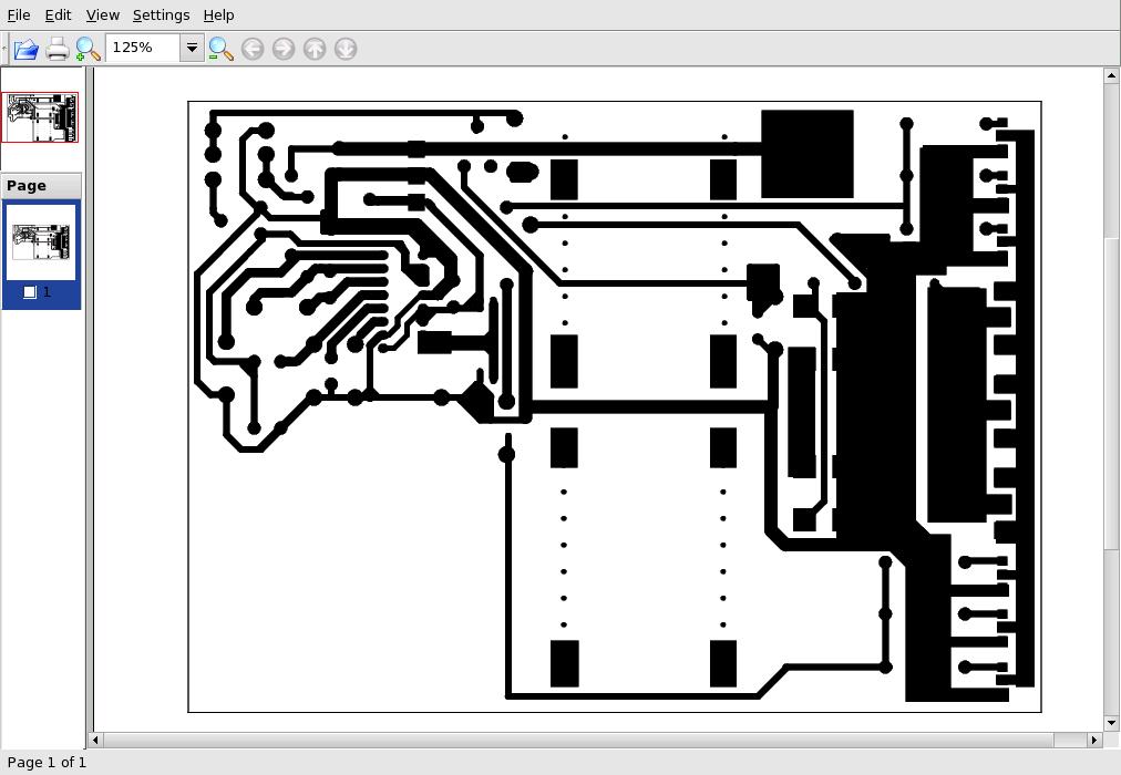
Its not done by an engineer so you get what you get... time to print it out.


Luckily the program had a driver for laser 300dpi and the old brother 730 I had bought across with me had just enough toner to print a page or two. (Moving onto an island is just so much fun).


I print it out on two transparencies (o/head projector sheets I think). I use two because this printer is pretty bad, and the toner is very low. I moved the image on the transparencies to different physical locations so that the flaws in the drum appear at different places on the layout.  very agricultural yes?


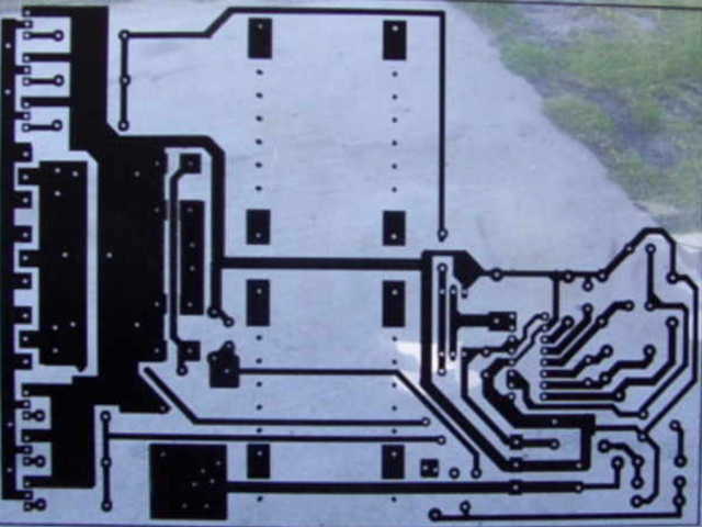
By taping the two transparencies together (on top of each other )we get a image that is mostly black where it should be in two layers. Any drum deficiencies only effecta single layer at differing places, so the theory was that tracks would be mostly covered.


This worked out as pictured here:


After rummaging around through the container outside, I found the picture frame I wanted and removed the glass from it, found the ammonium persulphate and breathed a sigh of relief..... over here you can't just go up to the shop. I've been waiting for a month for my fiberglass to turn up for a stator....still waiting.


So being lazy, I had gotten some pre-sensitized pcb boards from Wiltronics (on the net) and proceeded to sandwich the transparency between the green presensitised board and the glass from the picture frame.


Bewdy, now all I need is a UV light source. A flourescent for 20 minutes at 2" (havent got one out in the shed) or exposure to the sun for 1 minute or so.


So we wait for the sun to come out..........not coming out.....now its's raining again....bum.


The nice thing about oceanic weather is the complete unreliability of the weather. Its still raining, but now the suns out at the same time. I hold the board to the sun whilst standing undercover for 2 minutes....seems a long time to stand still and all the while thinking..... gosh this is high tech.


Now to develop the board.......oh no, can't seem to find the NaOH. When this happened  on the mainland we had a dishwasher, and the powder for it was caustic, and could be relied upon to act as developer....a shed in the middle of a paddock does not have a dishwasher. A quick test with the clothes washing powder yeilded no result...damn people frendly wash powder.......I did the unthinkable............


Went in and had a cup of coffee and brewed over my delimma....The good lady wife suggested oven cleaner......silly women..bloody oven cleaner that won't work says me...


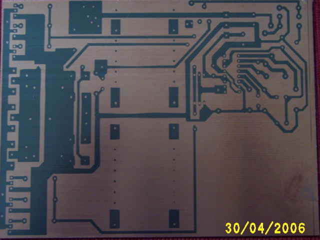
It was ten minutes later that I looked with satisfaction at my nicely developed board:


sheepishly went back in to inform she who must be obeyed that she was right, and I was wrong.....some days it don't pay to get outta bed.


Scrabbled around the shed looking for a suitable container to etch the board in. It must be corrosion-proof, disposable, tough, and I decided a 5kg plastic nail box for 4" bullethead nails looked perfect......soo out they go.


Armed with the newly aquired "etching tank" I added about a tablespoon of ammonium persulphate to 1/2 inch of hot water, and dumped the board in.


I sloshed the board around in the mixture for ten minutes.......I've had enough, it's too slow.....add more ammonium persulphate.....little bit more.....now I can see it peeling off (small exaggeration). it's almost done:


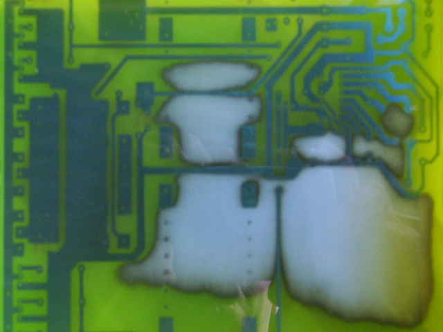
Note the lovely yellow nail container (i mean etching tank.).... Decided that makes it go faster.


Well half the day is gone and we have a board that needs drilling.  It was some time later that I found the minidrill, and importantly the mini-bits that go in it,and filled the desktop with another bunch of tiny holes. I have discovered that the drill drills quickly through the fibreglass, and that the trusty bench is at a different rate and sound so I know instinctively to move on to the next hole.. Good for me ..not good for the bench.


Well the next hour was used to load the board as per this overlay:


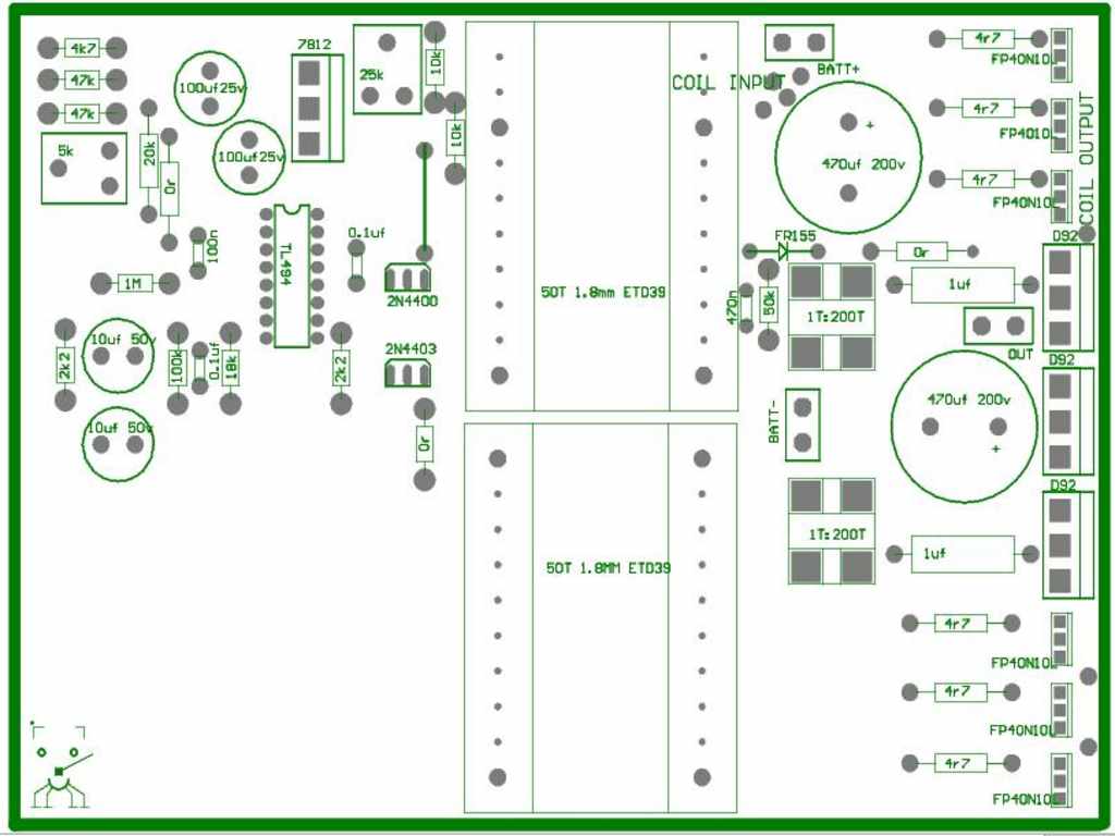
There is no trick to this, I use an ic holder to take the tl494 so that if I destroy it in testing, it is easy to replace. The coil is stolen from the original one I built a few days ago (50t ETD39)

It ends up looking like this:


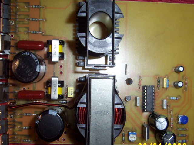
So yes it can be done easily from scratch... design, board design, load and test in a single day.... This makes it very easy when compared to making the turbine itself


Testing was as follows:

 Tentativly hooked up the power and the load, and the poor layout of the design was immediatly apparent. The waveform was ok down at lower levels, but started to wobble around a bit at higher levels. A 470n cap across the 1M resistor on the l/hand side of the overlay stopped the spurious voltage spikes, and the fets ran cool at 200W input for about two minuites. The diodes warmed up mildly, but that was all. At 300W, my battery on the recieving end was getting far too much charge and was held for only long enough to feel a slight warming of the fets.


It can be noticed that there is provision for a second coil, which I havent tried yet, but will wind it the same as the first inductor, and this should increase our power handling to well over 600W.


Just to get a better idea of how the switching wave was, I pulled out 5 of the 6 fets to find how heating went with only one to carry the switching current. 100w warm.. 200W nice and warm after a minute or so, 300W, now it needs a heatsink. Not superhot, but you could tell that without cooling, it would last only a few minutes.


All in all, very happy with the output. Whoever asked for a booster to drive 1 12v battery to charge another.12v battery.. this will do it at 20-25A or more in this config, or if the second inductor works as planned, 40-50A.


I don't have a copy of the circuit, as I made parts of it up as I drew the board. (I can hear the sounds of discust by people who design things properly. It is based on the circuit from Oatley electronics

http://oatleyelectronics.com/pdf/k098.pdf


The voltage regulator is different from this but same as silicon chip version...no circuit of this I'm afraid. Just reverse engineer the board. The output stage is roughly as Flux had described, and the current sense and voltage sense are last minute additions on the layout board.


The current reg will need a slight mod to use as a boost converter as per Flux, and I don't have the proper hall effect diodes over here, but if we were to sense the three phase by way of the singleturn current sense you could achieve roughly the same thing. (one line of "before the bridge diodes" of the genny output)


All in all, it was to show the folks out there that it is not the smoke and mirror enterprise that mppt has been seen as.....no one will give a clear and concise circuit and layout for that. why...I don't know, but Flux's setup is almost as efficient as a good mppt, and has redundency and simplicity built in, and is a 1 day project... and if you don't have to design the board and circuit, it is half a day project.


This current one will suffice for a large alternator if used with two coils. Further testing will show the upper-limits of this device, but 12v-24v is  easy. It should do every bit as well at higher voltage, and it's wattage will probably increase as well, as the currents will be less.


The old test bed is this one...


here it sports some heat sinks as i tried a 'what will she do mister.... 40A input fets still held together, but started to warm fairly fast.... certainly not dangerously so. The battery fizzed loudly, so stopped the test to destruction...spoiled my fun a bit.


If anyone is interested the board layout in pcb format for autotrax is boost5.pcb in my files. I will try and get hold of the hall effect np25 that flux suggests and do another more closely modelled along the lines of Flux's latest circuit ( if he doesn't mind, or isn't going to present a project for it )


It has one drawback as a standalone power supply. It relies on the recieving batteries as a voltage clamp. It will require a static load to keep it under control without this clamp..... will look into this, as with this solved, it may be a useful step-up converter in it's own right


still havin fun..............oztules

« Last Edit: May 04, 2006, 03:15:43 AM by (unknown) »
Flinders Island Australia

commanda

  • Hero Member
  • *****
  • Posts: 731
Re: 300w boost converter ..take 2
« Reply #1 on: May 03, 2006, 10:22:37 PM »
smoke and mirror enterprise that mppt has been seen as.....no one will give a clear and concise circuit and layout for that. why...I don't know,


If you're referring to me, the answer is very simple.

A: I'm busy

B: I'm slack

C: Necessity is the mother of invention, and the "necessity" isn't yet urgent enough to push it to the top of the "must do" pile.


However, there is a photo of the first prototype board and a fairly good description of the circuit in my diary. The second prototype is actually etched & drilled, ready to load. I won't publish the circuit until such time as it has been tested to my satisfaction, and I'm confident that there aren't any major faux pas.


Amanda

« Last Edit: May 03, 2006, 10:22:37 PM by commanda »

willib

  • SuperHero Member
  • ******
  • Posts: 2414
  • Country: us
Re: 300w boost converter ..take 2
« Reply #2 on: May 03, 2006, 10:30:00 PM »
oztules i found a nice description of the TL494 in pdf format..


http://www.otherpower.com/images/scimages/2965/TL494.pdf 337Kb


i have a power supply that uses a DBL494 that is the same thing , different company..

« Last Edit: May 03, 2006, 10:30:00 PM by willib »
Carpe Ventum (Seize the Wind)

oztules

  • Hero Member
  • *****
  • Posts: 1477
  • Country: aq
  • Village idiot
Re: 300w boost converter ..take 2
« Reply #3 on: May 04, 2006, 12:54:28 AM »
No Amanda, yours is not the type of device I envisage that should be referred to in this context.


From my observations, you are working steadily towards your chosen system, and are publishing your ideas and findings as you progress, from the tacho to the cunning meter systems, and I am guessing this is how you will continue to progress towards your ends. Pushing you is not my intent.


I am of the opinion that the system you are referring to is specific to your requirements and would not have been considered generic.


Nor would yours be suitable to be plugged into a 100Amp 12v output and expected to survive, but rather a small amps at high voltage, which is contrary to the majority here.


I have not seen you peddle your ideas as a solve all system fixing device....but rather a "this is what I am doing, if you wish you may too" type system.


All in all you hadn't crossed my mind (small as it is) to come into critisism in this context.


That said, I will continue to look forward to your posts on this subject, as you are approching it from an interesting perspective, and I have no doubt I will learn from your writings.


"C: Necessity is the mother of invention, and the "necessity" isn't yet urgent enough to push it to the top of the "must do" pile.".... in my case lousy windy weather and no fiberglass for my stator (waiting for 6 weeks now) has pushed it to the top of the pile.


Too cold and windy to fence, fish, play farmer bloggs etc, but just right to start to do some insideish projects..... I'd rather be building the stator..... but this will allow me to change its charastics before I wind it i guess.


hmmm....busy slackness.... trying to grapple with this :)


Have fun.............oztules

« Last Edit: May 04, 2006, 12:54:28 AM by oztules »
Flinders Island Australia

oztules

  • Hero Member
  • *****
  • Posts: 1477
  • Country: aq
  • Village idiot
Re: 300w boost converter ..take 2
« Reply #4 on: May 04, 2006, 01:08:01 AM »
Nearly all computer power supplies I have come across have used the tl494  (or its clones KA7500) It must be one of the most used pwm chips in the world. The device in the picture uses a KA7500 freshly stripped out of an old power supply (chinese AT type).


So just about any computer power supply could be used to build this thing. The highspeed electro's, output caps pushpull trannies etc.

« Last Edit: May 04, 2006, 01:08:01 AM by oztules »
Flinders Island Australia

commanda

  • Hero Member
  • *****
  • Posts: 731
Re: 300w boost converter ..take 2
« Reply #5 on: May 04, 2006, 02:57:00 AM »
would not have been considered generic.


Actually, the mppt controller itself should be very generic. Apart from scaling a few parameters to suit, it should be able to be used anywhere.


Problem is, it takes a certain minimum amount of nouse to apply it successfully. Probably never going to be a turn-key solution for the neophyte. Especially considering the DC-DC converters need to be designed & built pretty much on a per-application basis.


Amanda

« Last Edit: May 04, 2006, 02:57:00 AM by commanda »

WXYZCIENCE

  • Sr. Member
  • ****
  • Posts: 355
Re: 300w boost converter ..take 2
« Reply #6 on: May 05, 2006, 09:26:52 AM »
Looks good Oz. I see a number on that E-Core (ET0039? a little fuzzy)can you tell me a little more about it. Have you every tried toroids. Bill uses Easytrax for all of his board layouts. He uses an old plotter (HP 7475) and a light pen that replaces the ink pen. A white led and the guts of an old plotter pen. A tiny hole through a piece of copper foil from a circuit board. Then he makes a negative on line film on the plotter. Same process as yours, but reversed. Heats the etchant also, this speeds the process. We also run an old xyz cutter with the Easytrax. Joe.
« Last Edit: May 05, 2006, 09:26:52 AM by WXYZCIENCE »

oztules

  • Hero Member
  • *****
  • Posts: 1477
  • Country: aq
  • Village idiot
Re: 300w boost converter ..take 2
« Reply #7 on: May 05, 2006, 05:50:02 PM »
Hi Joe,

Working on a similar theory to yourself here..... i think its also known as "suck it and see" experimentation. Short term failure is an option, longer term understanding is a certainty.


This experimental board is a tidy up of the small board done a few days earlier, but simply tidying up the ratsnest on the desk and putting all the junk in one place. So the circuit board hols all the stuff including the inductors.


 To further investagations I designed the board with two inductors in order to see if it was as simple to scale up as I'd hoped..... It does seem to be the case.


The wave form is same as before (scope in my files). This is directly across the switch fet. With only 1 coil,efficiency drops below 90% at about 200W, with the two coils, this seems to keep the efficiency higher for much longer. (less resistance in the coils in parallel).


As a 12v battery charger  from another 12 v batt it is very good and stable. 20-30 amps.. no problem)(big deal who wants to do that anyway?) It needs a 470n cap in parallel with the 1m feedback resistor in this case.


For stand alone, the deadtime control (pin 4) needs about 220K from pin 4 to Vref. This stops it going into a runaway condition when there is no battery clamp on the output. What that could be used for escapes me as well.... but it is a very powerful voltage increaser in excess of 30v at quite high current.


For the operation it was loosly set to explore.... boost on an unstable input waveform...it appeared to be terrible. I connected it to a 1/2 wave rectified 50hz 10Amp transformer as an input, to mimic a fast spinning single phase mill. The resultant output into a battery was shocking above 2A.


This was caused from two things. As I increased the output, the rms output from the source transformer dropped . This fed directly into the voltage support for the tl494 (ka7500 in this case), and it dropped in and out of operating range at 50 hz...what a hash that made of the switching waveform.......


The second problem was that being single phase input, in every cycle we dropped through zero and so there was no voltage to boost, and so the boost fet tried to drain the filter cap on the Voltage regulator......splat she no work too good. If it was on three phase this would be masked some.


We could draw the chip power from the battery on the output... too easy


Being different, I decided it would be better to solve the problem from the input side so that it could be run as a power supply from a scrappy source. This required only a diode in the line from the input pad to the regulator. This allowed me to use the voltage peaks and filter and regulate them for the pwm chip and driver circuit, but the switcher fet couldn't drain this supply back through the diode...another failure... another lesson, another victory.


So that's where it is.

 The inductor was wound on the lathe from 1.8mm wire Neatly close wound for four layers....comes to about 54 turns or thereabouts. The frequency is so low (3khz) that it offers lots of flexability.


The core material is 3C80 (the numbers you can almost see), but any thing will do at these frequencies. The two small current transformers came from some junk psu. Could easily wind your own around a core, or use the input noise filter inductor from a standard psu and rewind the coils on that. I only used two to get enough current handling through the single loop at 40-50 amps....for the hell of it .


Does that tell you enough about this experimental fangdangle, just ask if not.


Have I used torroids.... yes but a bugger to wind the small ones..trying to feed the spool through the center is a drag. Did use them for multilpe drive of a H bridge once, and they offer good coupling, low noise emination, but i have around a hundered etd39 cores, and 200 smaller cores and formers to play with, they are easy to wind, and most importantly, they are here. Also have a dozen biggens for another  more powerful project later on.


Tell Bill to give the new...(1988 or so) autotrax a go... I like the dos progs much better than the window protels, although the screen and printer matching is easy with a windows version...and the spice etc.


As for Bill


Put a fire under him and lets see the 6v booster.:)


I'm interested how he drove the switcher and fets at this voltage, oscillator and auto tranny or is it secondary driven (using the power from the 12v batt not the 6v one)


If you can think of a use for this... your one in front of me, but i learn't quite a bit from it.


And yes I don't know what I'm doing, but I'm doing it anyway....and luvin it


Keep up you good work Joe, some of it is insperational


and I'll learn to spell when I grow up perhaps.


...........oztules

« Last Edit: May 05, 2006, 05:50:02 PM by oztules »
Flinders Island Australia

willib

  • SuperHero Member
  • ******
  • Posts: 2414
  • Country: us
Re: 300w boost converter ..take 2
« Reply #8 on: May 05, 2006, 10:41:01 PM »
"For the operation it was loosly set to explore.... boost on an unstable input waveform...it appeared to be terrible. I connected it to a 1/2 wave rectified 50hz 10Amp transformer as an input, to mimic a fast spinning single phase mill. The resultant output into a battery was shocking above 2A."


you are correct in that a three phase input to your device would produce much better results , ie a three phase rectified  alt never goes below zero..

i have a question .. you are charging a battery from a battery , are you able to control the output voltage at all , for example could your device charge at 24V? 36 or 48V ?

and what is the minimum input voltage?

« Last Edit: May 05, 2006, 10:41:01 PM by willib »
Carpe Ventum (Seize the Wind)

oztules

  • Hero Member
  • *****
  • Posts: 1477
  • Country: aq
  • Village idiot
Re: 300w boost converter ..take 2
« Reply #9 on: May 06, 2006, 12:03:23 AM »
"you are correct in that a three phase input to your device would produce much better results , ie a three phase rectified  alt never goes below zero.."


Yes Willib, but when your learning in a vacuum, the best result is maximim failure, and then working your way up to where you need to be...i'm a sucker for punishment.


The result when I isolated the pwm run chip and associated drivers from the pulsed input wave, led to a very satisfactory outcome. it only needed an isolating diode.


Had I started with a reasonable outcome from three phase input, I would not have known how crappy it was under lousy input condidions..:)


The output in it's current form is fluid to a certain extent. The pulse is controlled by the confluence of both the current return mixed with the voltage differential (reference voltage against the outputvoltage, tempered with the current transformer output. Pots 1 and 2 control their influence).


If you connect this up to higher voltage loads, it will try and drive them (if you twiddle the 5k pot). I haven't tested above 28v output thus far, but i assume that at some upper limit, the losses through efficiecy may deteriate. 50% pulse width  is a doubler, and it goes up from there in theory, the input voltage can be as high as you have fets for...


provided you diode isolate and use a decent resistor to drop the voltage to the regulator . Its(7805) max V is less than 40v (look up 7805 specs). So providing you stay below these limits using a resistor before the vreg, then the fet is the limiting factor. (assuming the output diode can handle it and the transients)


The inductor would have to be changed, or the frequency increased as you started to get further away from the impedance matching to the input....this is just a hunch/guess. Some one else may have to help you here, or I may do some tests.....havent got any loads over 24v at the moment thou.


If you tell me what you want, I'll tell you what to change to make it happen( if I can). The basic pwm, drive, and switchpart can do almost anything, just matter of changing a few ancillary bits to achieve it.... i can hear the purists rolling over in agony here, but this is my approach......just do it and make it work..more good fun.


The minimum voltage is really where the fets wont turn on cleanly, and I think the 494 undervoltages at somewhere around the 8 v mark (you have the pdf, it's too big for me and my memory is lousy) I think 10v may be about the lower limit. (I have taken it lower as the donor battery died, but it deteriates fairly soon below that)


The end game is to make the waveform as close to square and clean as you can, whilst achieving your objective.... the waveform is everything, as you move away from it's optimum, things go wrong quickly...efficiency and heat problems.


Hope this helps


...............oztules

« Last Edit: May 06, 2006, 12:03:23 AM by oztules »
Flinders Island Australia

willib

  • SuperHero Member
  • ******
  • Posts: 2414
  • Country: us
Re: 300w boost converter ..take 2
« Reply #10 on: May 06, 2006, 08:40:53 AM »
"The minimum voltage is really where the fets wont turn on cleanly, and I think the 494 undervoltages at somewhere around the 8 v mark (you have the pdf, it's too big for me and my memory is lousy) I think 10v may be about the lower limit. (I have taken it lower as the donor battery died, but it deteriates fairly soon below that)"


Yes but arent you assuming that your device is powered by the input?

if your device was powered by a seperate battery , how low of a voltage would work.?

the reason i'm asking is i've done some work with a 10ga. coil which produces some incredable current but at low voltage, i forget how low ,10 or 11V dc rectified seems to come to mind , but the current in one coil was enough to heat my "load" which was about 7 inches of 20 ga. wire.

« Last Edit: May 06, 2006, 08:40:53 AM by willib »
Carpe Ventum (Seize the Wind)

willib

  • SuperHero Member
  • ******
  • Posts: 2414
  • Country: us
Re: 300w boost converter ..take 2
« Reply #11 on: May 06, 2006, 09:00:58 AM »
let me clarify , 10-11vdc was a calculated figure of a 18 coil three phase alt using 10 ga. wire. i really gotta go back and check my notes
« Last Edit: May 06, 2006, 09:00:58 AM by willib »
Carpe Ventum (Seize the Wind)

oztules

  • Hero Member
  • *****
  • Posts: 1477
  • Country: aq
  • Village idiot
Re: 300w boost converter ..take 2
« Reply #12 on: May 06, 2006, 05:57:47 PM »
Can't say I had considered switching say 6v and using the  12v battery load to power the voltage requirements of the unit.


I'm guessing (over a morning cup of coffee ) that it should have no problems. In this case i will just lift the device power from the input pad, and connect it to the ouput battery. then I'll just fire it up as usual. I'll try charging a 12v batt from a 6v batt..... The idea of the drain being at a lower porential than the gate has me swimming a bit, but testing should tell the story....it mostly does.  and I'll learn something new I guess (for me anyhow)...


I'll try it today, or someone in the meantime will let us know.


I think it was you using a pic to generate square waves. That will probably do a better job than this "dumb" unit.... I haven't played with pics so don't know.... although the dumb version is easy to build and no programming....., you may get some staisfaction from expanding your experiment.


i'll try to do it today


have fun


................oztules

« Last Edit: May 06, 2006, 05:57:47 PM by oztules »
Flinders Island Australia

oztules

  • Hero Member
  • *****
  • Posts: 1477
  • Country: aq
  • Village idiot
Re: 300w boost converter ..take 2
« Reply #13 on: May 06, 2006, 06:54:55 PM »
sorry Willib, in the above post i said 7805, it should be 7812... 12v reg not 5v reg.
« Last Edit: May 06, 2006, 06:54:55 PM by oztules »
Flinders Island Australia

willib

  • SuperHero Member
  • ******
  • Posts: 2414
  • Country: us
Re: 300w boost converter ..take 2
« Reply #14 on: May 06, 2006, 07:36:13 PM »
Yes it was me with the pic16F88 it has  PWM and an a2d converter built in.

it reads the voltage at the input to the a2d and outputs a corresponding pwm on/off ratio.

the frequency can also be programmed

the input to the a2d is just a simple voltage divider ( varible resistor or pot) between +5v and ground the wiper is the input to the pic.

at the moment it is happily proving me with a varible current to cut up foam

« Last Edit: May 06, 2006, 07:36:13 PM by willib »
Carpe Ventum (Seize the Wind)

oztules

  • Hero Member
  • *****
  • Posts: 1477
  • Country: aq
  • Village idiot
Re: 300w boost converter ..take 2
« Reply #15 on: May 06, 2006, 09:15:23 PM »
replace the cutting wire with an inductor and a diode (fast switching) and your on your  way to the races.  it's that simple. In your case the pot provides the pulse width to control output voltage. Use an in line resistor to test with so you don't go over current at first go.   maybe a headlight or two.


..........oztules

« Last Edit: May 06, 2006, 09:15:23 PM by oztules »
Flinders Island Australia

willib

  • SuperHero Member
  • ******
  • Posts: 2414
  • Country: us
Re: 300w boost converter ..take 2
« Reply #16 on: May 06, 2006, 09:56:55 PM »
i think you underestimate the complexity of the chip you are using , if i did use an inductor and a diode , what about deadtime control , my system would have no deadtime control at all

maybe its not an issue at these frequencies?
« Last Edit: May 06, 2006, 09:56:55 PM by willib »
Carpe Ventum (Seize the Wind)

oztules

  • Hero Member
  • *****
  • Posts: 1477
  • Country: aq
  • Village idiot
Re: 300w boost converter ..take 2
« Reply #17 on: May 06, 2006, 10:32:03 PM »
If you check the board i'm using, the deadtime is used only for the first second of operation to initiate a soft start. (sexy but not necessary) Then it becomes fully turned on. It plays no further part in the system I used.


The 10uf cap drives pin 4 to vref potential on turn on, and then the 100k bleeds this back to gnd potential over the first second. After that it is grounded until next power up..... what dead time.


I did use it in the test for stand alone power supply use, (put 250k from vref to pin 4, set max pulse to predetermined value), but that was only because I couldn't current control the circuit at full power.... no pulse width left to generate an ac current in the current transformer...I cheated and used deadtime to limit upper power drive thats all.


It's not a frequency problem, its a control problem. Provided you have control over the pulse width, you have control over the output. Provided you have some softness built into the system (current resistor or light globes to absorb the current surge in case of distress), you can try all sorts of things. If you can build in some reliable current control feedback, it's damn near impossible to destroy it....(and I'm just the bloke to try to.).


...........oztules

« Last Edit: May 06, 2006, 10:32:03 PM by oztules »
Flinders Island Australia

willib

  • SuperHero Member
  • ******
  • Posts: 2414
  • Country: us
Re: 300w boost converter ..take 2
« Reply #18 on: May 06, 2006, 11:37:12 PM »
ok ,i'm not seeing something here, if i hook the inductor and diode where the motor and diode are in the photo

 is the output, across the inductor?


« Last Edit: May 06, 2006, 11:37:12 PM by willib »
Carpe Ventum (Seize the Wind)

willib

  • SuperHero Member
  • ******
  • Posts: 2414
  • Country: us
Re: 300w boost converter ..take 2
« Reply #19 on: May 06, 2006, 11:43:04 PM »
in series with the inductor ?
« Last Edit: May 06, 2006, 11:43:04 PM by willib »
Carpe Ventum (Seize the Wind)

oztules

  • Hero Member
  • *****
  • Posts: 1477
  • Country: aq
  • Village idiot
Re: 300w boost converter ..take 2
« Reply #20 on: May 07, 2006, 12:02:35 AM »
throw away the motor and its freewheel diode, and the capacitor (d2 and c8) The coil replaces the motor ie betweem b+ and drain on the mosfet.


Your new highspeed diode (anode on the fets drain, cathode to the battery to charge) takes it's power take off from the drain of the fet.


I initially used that circuit but didn't allow for current regulation.....boom. If I had had a headlight in series with the input b+, it would have been ok to test with.


The fet "shorts the coil to ground" and effectively makes it into an electromagnet. When the fet opens again the stored energy can be drained off with the diode to the load. The longer the pluse is held, the greater the time to generate a stronger field..until saturation if too long.


This is not quite how it happens, but it makes it easy to "feel" how it all interacts.

So I look at it as "the longer the time (pulse width) the bigger the output "


It's not accurate, but it's like saying we suck soda up with a straw. It seems right and we can understand it better than someone saying that really the soda pushes up the straw by being driven up by a pressure differential between your mouth and the airpressure in the surrounding atmosphere.  


............oztules

« Last Edit: May 07, 2006, 12:02:35 AM by oztules »
Flinders Island Australia

commanda

  • Hero Member
  • *****
  • Posts: 731
Re: 300w boost converter ..take 2
« Reply #21 on: May 07, 2006, 12:35:14 AM »
Interesting to note that the pdf circuit published by Oatley  Electronics, the DTC (dead time control) pin is actually labelled as inhibit.


Totally off-topic I know, but I just used that kit from Oatley to build a 12 volt in, 3.6 volt out buck converter to power the lights on my pushbike.


Amanda

« Last Edit: May 07, 2006, 12:35:14 AM by commanda »

willib

  • SuperHero Member
  • ******
  • Posts: 2414
  • Country: us
Re: 300w boost converter ..take 2
« Reply #22 on: May 07, 2006, 12:35:59 AM »
would it look like this when hooked to an alt


http://www.otherpower.com/images/scimages/2965/oz_circuit.JPG

« Last Edit: May 07, 2006, 12:35:59 AM by willib »
Carpe Ventum (Seize the Wind)

oztules

  • Hero Member
  • *****
  • Posts: 1477
  • Country: aq
  • Village idiot
Re: 300w boost converter ..take 2
« Reply #23 on: May 07, 2006, 01:32:32 AM »
looks the goods to me. What did you draw it in?


A big cap across the input (+to -) would help too.


only gonna get comfortable with this by leaping in and doing it.


............oztules

« Last Edit: May 07, 2006, 01:32:32 AM by oztules »
Flinders Island Australia

willib

  • SuperHero Member
  • ******
  • Posts: 2414
  • Country: us
Re: 300w boost converter ..take 2
« Reply #24 on: May 07, 2006, 01:39:11 AM »
http://www.linear.com/index.jsp

on the left side  twards the bottom , look for free switchercad download
« Last Edit: May 07, 2006, 01:39:11 AM by willib »
Carpe Ventum (Seize the Wind)

oztules

  • Hero Member
  • *****
  • Posts: 1477
  • Country: aq
  • Village idiot
Re: 300w boost converter ..take 2
« Reply #25 on: May 07, 2006, 02:25:36 AM »
very odd indeed that they chose to call it inhibit pin.


In nearly every case of finding a 494 in pwm supplies, pin 4 it is used as an inhibit pin ( usually driven by a scr or similar latching system..... ) to effect shutdown from over current or some other catastrophic event.....then I'd call  it an inhibit pin too.


Here they use a control voltage to give a linear deadtime variance ( to achieve a nice soft start) and call it  an inhibit pin... This is one of the few times I've seen it used as a dead time control...


My diary, so I declare it not off topic "Totally off-topic I know, but I just used that kit from Oatley to build a 12 volt in, 3.6 volt out buck converter to power the lights on my pushbike"


It shows that it is a nice simple pwm circuit that can be adapted to all kinds of uses... is that generic?


pics?


................oztules

« Last Edit: May 07, 2006, 02:25:36 AM by oztules »
Flinders Island Australia

commanda

  • Hero Member
  • *****
  • Posts: 731
Re: 300w boost converter ..take 2
« Reply #26 on: May 07, 2006, 04:20:03 AM »
pics?


Bit late for that. It wasn't a project I envisioned as being for the general edification of the populous at large. It was more of a necessity that made its way to the top of my to-do list, and so got done. Though I must say the voltage feedback mechanism was something of a stroke of genius. It uses the two existing resistive divider networks on the Oatley pcb. I inserted a 3.6 volt zener in the one coming from +12, so the drain of the fet would regulate to Vcc - 3.6. Used a TL431 shunt regulator with a pot to get the zener. The inductor is a 220mH toroid fitted to the back of the pcb. A bolt goes through the case, through the centre of the toroid, and through the pcb, to hold the whole thing in place.


This board, a 12 volt, 1.2 AH SLA, on/off rocker switch, 2 dc sockets for output to the front & rear lamps, another dc socket to plug in a charger, and some foam to hold the battery in place, all resides in a plastic jiffy box cable tied to the frame of the bike.


All I have to do now is get my fitness level back up sufficiently to ride the 6Km each way to/from work. I could use a small solar panel to charge the battery whilst the bike is parked at work. A few hours of afternoon sun should be more than sufficient.


Amanda

« Last Edit: May 07, 2006, 04:20:03 AM by commanda »

oztules

  • Hero Member
  • *****
  • Posts: 1477
  • Country: aq
  • Village idiot
Re: 300w boost converter ..take 2
« Reply #27 on: May 07, 2006, 05:50:54 AM »
So.. whats it feel like to have the worlds most high-tech bicycle.


and to think, you did all this so you could torture yourself every day?.... and it got to the top of the to do list....hmmm doodles in sand with finger.......thinks to self......self, these northerners are indeed odd creatures:)


............oztules:)

« Last Edit: May 07, 2006, 05:50:54 AM by oztules »
Flinders Island Australia

oztules

  • Hero Member
  • *****
  • Posts: 1477
  • Country: aq
  • Village idiot
Re: 300w boost converter ..take 2
« Reply #28 on: May 07, 2006, 06:10:53 AM »
Ok Willib,

Tried the low voltage to 12 volts by using the 12volt battery to be charged  as the source of the power for the pwm and fet drive.


The b+ to the coils started at 9v (Makita drill battery)


Started out with about 8A @ 9v 72W for an output current of around 5A@ 12.9 64W things changed quickly as the supply batt dropped off quickly.


As it got to 3v-4v around 30A it still drove the 12v battery at 12.9v around 3A These low voltage figures are rubbery as the voltage dropped quickly, and trying to measure everything got out of hand, but it looks as though the system will indeed operate down to very low volts.


Hope that helps to clear up a few things.


..............oztules

« Last Edit: May 07, 2006, 06:10:53 AM by oztules »
Flinders Island Australia

willib

  • SuperHero Member
  • ******
  • Posts: 2414
  • Country: us
Re: 300w boost converter ..take 2
« Reply #29 on: May 07, 2006, 06:30:33 AM »
thats great ! good morning BTW yawns

i'm glad it worked .

did you dl switchercad?
« Last Edit: May 07, 2006, 06:30:33 AM by willib »
Carpe Ventum (Seize the Wind)

Gary D

  • Sr. Member
  • ****
  • Posts: 442
Re: 300w boost converter ..take 2
« Reply #30 on: May 07, 2006, 08:02:47 AM »
Oz, I was wondering if you split/separated the inductor holder to keep "saturation" from happening? It looks similar to a spool? Or was this not necessary? I have these diaries on my hotlists for further referance (Flux matching the load too). Never etched a pcb. but a standard breadboard should do the same thing, in a larger size? Trying to keep questions to a minimum since I don't think it would wise for me to expect things not to "smoke" at the worst of times ie. high windspeeds( with my few experiences into electronics). Will go with 12 volt system (easy to jump to 24, just takes a few battery reroutings and replace with a higher voltage inverter ($)...  Gary D.
« Last Edit: May 07, 2006, 08:02:47 AM by Gary D »

willib

  • SuperHero Member
  • ******
  • Posts: 2414
  • Country: us
Re: 300w boost converter ..take 2
« Reply #31 on: May 07, 2006, 02:14:34 PM »
oz , what size inductor would you recommend > num turns , no core, or core?

the output current dosnt seem to rise as quickly as the input current..

but it works!!

i'm using 12V for input and 12 V for output (for now)

since i can control the pulse from flat off to full on , i've limited the input current to 3A but the output didnt go above 20mA, it was charging though because it went fron 12.27V to 12.29V !!

but somethig is amiss, it has to be the inductor

ps i'm also using a standard diode
« Last Edit: May 07, 2006, 02:14:34 PM by willib »
Carpe Ventum (Seize the Wind)

commanda

  • Hero Member
  • *****
  • Posts: 731
Re: 300w boost converter ..take 2
« Reply #32 on: May 07, 2006, 03:30:31 PM »
The answer to your musings, and my apparent madness, is quite simple.


The ridiculous cost of petrol.


It's either that or trade the RX7 sportscar on a Toyota Prius.


Some form of personal electric-powered motorvation, like is seen at the motor show or beyond 2000, would be ideal. But of course, you can't actually buy these in Australia yet. And you never will while ever the Government rakes in obscene amounts of petrol excise.


</rant>


Amanda

« Last Edit: May 07, 2006, 03:30:31 PM by commanda »