Author Topic: Testing 7.5hp conversion with capacitors  (Read 4307 times)

0 Members and 1 Guest are viewing this topic.

zubbly

  • Sr. Member
  • ****
  • Posts: 371
Testing 7.5hp conversion with capacitors
« on: September 16, 2006, 10:53:53 PM »
hey everybody!


its been about a month and a half since i got the 7.5hp conversion flying. the wind gods have not been very nice and have been holding back on the wind. i did manage to be home a few times when we got some fair wind though. best i have seen so far is approx. 2kw into my element bank. my heating bank is an 18kw @208 volt 3 phase unit. comes out of a roof top heater as back up with natural gas being the main heat source.


the element bank consists of 6 nichrome wire elements. the original connection had the unit split into two parts. each part was connected delta, and the two parts were then paralelled. what i am doing my testing with is just 1/2 of the unit connected star. the ohm reading when connected star is 28 ohm between any two phases.  my gen, connected at 1 star connection, measures approx 2 ohm between any two phases. the gen is a 12 pole unit, designed to give 240 volt at 600 rpm unloaded voltage.


i have been testing to date using voltage relays to pull the first half of the heating bank on line at approx 85 volt, and the second half of the bank comes in at approx 140 volt line voltage. i have been using 208 volt 3 pole relays to carry the load. i have rectified the control voltage to DC which does a good job of keeping the contactors from chattering.


problem so far has been that most of the time, the genny is running under 85 volt, and basically i am loosing everything under that voltage. :(

lately i have seen some discussion on the board about using capacitors to work with the gen and elements for a heating system. as i understand it, the idea with the caps is to change the power curve from squared to cubed.


i have done this today with the caps connected in series with the 3 phases. i basically removed the plate on the heating element bank that made the star connection and put the caps in series with the 3 phases. when you take an ohm reading between any 2 of the 3 input studs on the element bank with the caps connected, it basically shows an open circuit. the gen starts up in the smallest breeze with the element and caps bank direct connected to the gen.


first, i will show you a few pics of my messy panel, the capacitors, and the element bank.  then the results.


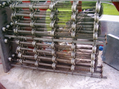
the 18 kw 208 volt 3 phase heating bank


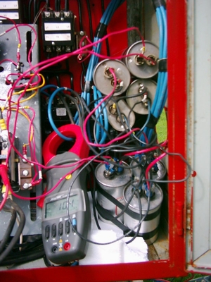
here you can see some of the capacitors. some of them are hidden.  at present, i have 200 MFD (2x60mfd plus 1 80 MFD in paralell) per phase. they are 370 and 440 volt caps (motor run caps)


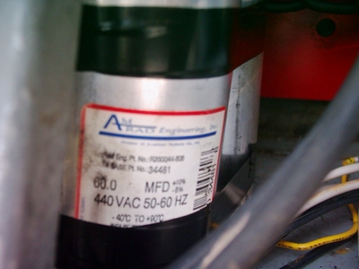
here is one of the 60MFD x440 volt caps


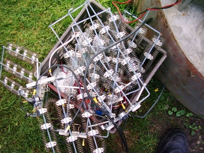
here is a bunch of other elements i have been testing with in different configurations. each one is a 3.4 kw 230VAC element.


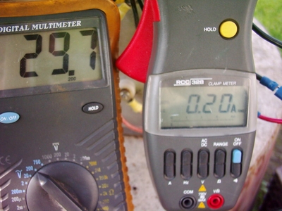
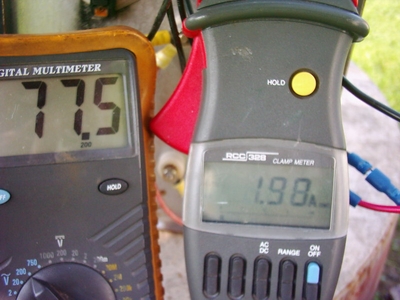
i have taken pictures of the meters showing the output. the meter on the left is the AC voltage, the meter on the right is the amperage. the formula i use to determin wattage output is  volts X amperage X 1.73     the weather man says winds today are 10kph (6.2 mph) it might have been a little more with the gusts. the results are quite interesting.


29.7 volt x .2 amp = 10.27 watt


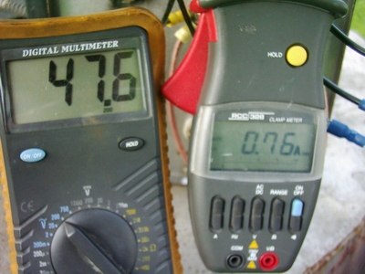
47.6 volt x .76 amp = 62.58 watt


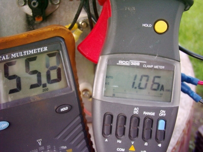
55.8 volt x 1.06 amp = 102.32 watt


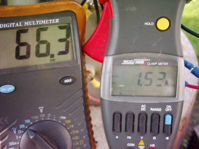
66.3 volt x 1.52 amp = 174.34 watt


77.5 volt x 1.98 amp = 265.46 watt


the results i find are quite interesting.  seems to be a huge jump in watts with little gain in voltage.  the last 2 tests show approx a 90 watt jump with 11 volt gain.


if someone with a little more insight as to what is going on here, please share your wisdom so that i may understand this better myself.  i anxiously look forward to some good strong wind to see what happens with total output.


thats it for now folks, and when i have some better wind i shall share the results with you.


zubbly

« Last Edit: September 16, 2006, 10:53:53 PM by (unknown) »

RP

  • Hero Member
  • *****
  • Posts: 722
  • A dog with novelty teeth. What could go wrong?
Re: Testing 7.5hp conversion with capacitors
« Reply #1 on: September 16, 2006, 05:15:34 PM »
Basically the capacitors are acting as a "frequency controlled resistor".  If you have a meter that reads frequency or for that matter a tachometer I think you'll see this.


As the rpms go up you're seeing the voltage rise (as expected).  Also however, the frequency of the AC goes up, so the capacitors conduct more, so more current is being pulled from the coils, so the voltage cannot rise as much as you'd expect due the the higher load.


Think of it this way:  If you had a 10 stage progressive dump load controller hooked to a tachometer, you'd see something similar.  The speed goes up, the wattage goes up but the voltage kind of levels off as more loads come on line.


Hope this helps

« Last Edit: September 16, 2006, 05:15:34 PM by RP »

electrondady1

  • SuperHero Member
  • ******
  • Posts: 3120
  • Country: ca
Re: Testing 7.5hp conversion with capacitors
« Reply #2 on: September 16, 2006, 07:06:29 PM »
a great experiment zubbly.


those numbers ARE interesting!

and the timing is perfect!

so the ratio of resistance, load to geni was 28/2 or 14/1


did you use much math and science to to come up with 200mfd value ?

did the caps get hot?

am i right in thinking that the 265 watts represents about 1/3 of the energy that was going into the elements?

almost 800 watts in total?

« Last Edit: September 16, 2006, 07:06:29 PM by electrondady1 »

dinges

  • Hero Member
  • *****
  • Posts: 1294
  • Country: nl
Re: Testing 7.5hp conversion with capacitors
« Reply #3 on: September 16, 2006, 07:15:28 PM »
I'm no expert on the matter, but I'd not just take the current and voltage readout and multiply them to get power. There's a difference between real power (kW) and kVA.


If you do multiply volts & amps, you assume that voltage and current are in phase. However, introducing capacitors introduces capacitive reactance in the (formerly purely resistive) system. It's the difference between kVA and kW; cos-phi is a measure of the phase shift between voltage and current.


To get a more detailed idea of what's going on I'd try to connect the system to an oscilloscope to measure the phase difference between voltage and current.


Anyway, I'm certain of one thing: if you add (capacitive) reactance, you can no longer multiply volts & amps to get at watts. Try measuring or determining the cos-phi of the system.


kW = kVA * cos(phi)


If you've got a big phase shift, your cos(phi) term will become lower. You were measuring kVA (volts*amps), however, your real power (kW) will go down as cos(phi) decreases.


Notice that, as long as volt & current are in phase, cos(phi) = cos(0) = 1, so kW=kVA. In that case, you can multiply volts & amps to arrive at real power.


Might also try to get hold of a measuring instrument that's capable of measuring cos(phi) directly. Some of the better DMMs can measure this.

« Last Edit: September 16, 2006, 07:15:28 PM by dinges »
“Research is what I'm doing when I don't know what I'm doing.” (W. von Braun)

Putte

  • Newbie
  • *
  • Posts: 25
Re: Testing 7.5hp conversion with capacitors
« Reply #4 on: September 17, 2006, 12:07:54 AM »
Nice looking Zubbly.


Fun to see that some is trying with capasitors and maby find out the best formula.


I did meter the voltage drop over the resistor to read the power how far would that be from the real power?


Putte.

« Last Edit: September 17, 2006, 12:07:54 AM by Putte »

Putte

  • Newbie
  • *
  • Posts: 25
Re: Testing 7.5hp conversion with capacitors
« Reply #5 on: September 17, 2006, 06:11:03 AM »
This is perhaps not right at all but.


When i did meter the watts on my experiment i meter the voltage drop over the resistor volt*amp*3= Watts Now if that is right i have now idea? But i hope some one will explain how bad that is.


Putte

« Last Edit: September 17, 2006, 06:11:03 AM by Putte »

zubbly

  • Sr. Member
  • ****
  • Posts: 371
Re: Testing 7.5hp conversion with capacitors
« Reply #6 on: September 17, 2006, 01:09:23 PM »
hey RP!


thanks for the reply. simple and easier to understand with that thought.


thanks,

zubbly

« Last Edit: September 17, 2006, 01:09:23 PM by zubbly »

zubbly

  • Sr. Member
  • ****
  • Posts: 371
Re: Testing 7.5hp conversion with capacitors
« Reply #7 on: September 17, 2006, 01:21:48 PM »
hi electrondady1,


for some reason, it didn't seem to show above each reading how i showed how i calculated the wattage output. basically, volts x amps x 1.73 (the 1.73 is the averaging of all 3 phases put together). so basically, 265 watts total heat from the elements. from reading some of the other comments, there definately may be more accurate forms of measurment to calculate wattage output when you use capacitors, but for now, i will stick with this method for simplicity. it may not be that accurate, but good enough to get an idea of how it is working.


i didn't use any math to calculate the capacitors. i simply started out with 120 MFD per phase. i then added an extra 80 MFD per phase, and found that the current output was only .2 of 1 amp more tested against the 120 MFD at one of the same lower test speeds. adding a lot more MFD per phase may make a worth while gain in output, but i basically have run out of capacitors.


zubbly

« Last Edit: September 17, 2006, 01:21:48 PM by zubbly »

zubbly

  • Sr. Member
  • ****
  • Posts: 371
Re: Testing 7.5hp conversion with capacitors
« Reply #8 on: September 17, 2006, 02:01:39 PM »
hey all!,


had a little more wind today and did some more testing.


here is what i found:


using the caps that i now have connected (200 MFD per phase) the gen starts up as though there was no load attached to it at all. this is great and makes for a very simple way to directly connect to an element bank and not have to worry about stalling the blade before it gets going.


the gen was very responsive to increases in wind, and also the voltage continued to rise as current did as well. voltage output today peaked at approx 85-90 volt with an increase in amperage very similar to that of the lower rpm tests. didn't have the camera outside at the time, so no pictures.


i picked one particular voltage output of the capacitor system to compare to the way i have been testing all along. at 50 volt output, the current was 1.2 amp using the caps.

i then removed the caps and connected back up to the heating bank using my controls. when the gen reached 50 volt, i manually pushed the contactor in and found that current was 2.1 amps. basically as of now, the system has more output without the caps than with. also comparing at higher voltages, the non capacitor system still out performed the capacitor method. if i had more capacitors, i would have tried them. so as of now, i will be sticking with the non capacitor method for this heating season as winter is fast approaching and am anxious to complete the hook up to my house heating system.


the previous pictures show my panel just for experimenting. most of it is for future use and selection of what i want at the time for heating or batt charging will be done with the flick of a switch. star/delta has been incorporated into the controls and will test it all out next year.


i finished the small control panel that will be mounted right on the air duct system today. it is simply 2, 3 pole contactors and 2, 208 volt fan relays. the fan relays have a small screw inside that the cut in voltage can be set up with. first experiments had everything chattering at low voltages and also because the frequency was also low. what i did was to rectify the voltage for control from 2 of the 3 genny lines and feed the ac coils of the contactors and fan relays with it. results are excellent. you only hear a slight vibration from the first fan relay until it pulls in. the rest of the coils all operate perfectly smoothly untill the voltage drops low enough for the fan relays to kick out and drop out the main contactors.


as i have it set up now, the first contactor pulls in at 80 volt (checking from the genny lines AC voltage), and powers the first half of the heating bank whick is connected in star.  the second contactor pulls in at 100 volt from the genny lines and feeds the other half of the heating bank. when wind slows down, the second contactor drops out at approx 50 volt. if wind is sufficient, the first contactor remains engaged. if the wind slows down more, the first contactor drops out at approx 30-35 volt.  it actually works quite slick, and i am quite happy with it. none of the contactor or fan relay coils seem to get any more than a little warm.


on my 1.5hp conversion, i have been running a star delta control, controled with a vacumm switch for just about a year now. the contactor coils are also AC voltage, but are fed with rectified voltage, and have shown no problems so far.


here is 2 pictures of the control i will be using for the heating system. 2 30 amp 3 pole contactors, 2 fan relays, 1 bridge rectifier for the control voltage. everything you see is salvage except the bridge rectifier.


once winter sets in, the wind in this area greatly improves, and i will be able to get some much better readings of the system.


zubbly

« Last Edit: September 17, 2006, 02:01:39 PM by zubbly »

Flux

  • Super Hero Member Plus
  • *******
  • Posts: 6275
Re: Testing 7.5hp conversion with capacitors
« Reply #9 on: September 17, 2006, 02:16:00 PM »
The power measurement is ok as long as the volts are across the resistors. Voltage across the machine terminals before the capacitors will give VA.


You need to start with capacitors with a reactance comparable with the resistance at your low wind speeds, perhaps a bit lower.


In low winds the impedance will result in a current considerably lower than without the capacitors. As the speed and frequency rises the capacitive reactance will fall and the voltage across the resistors will rise and the capacitor voltage fall. At full load the capacitor reactance should be significantly below the resistance and the resistance should be full load for the alternator.


At full load the capacitors will present a slightly leading power factor to the alternator and partly neutralise its leakage reactance( inductive). You should get more output than loading with resistors alone.


If you stall in low winds use smaller capacitors.

Flux

« Last Edit: September 17, 2006, 02:16:00 PM by Flux »

windy

  • Full Member
  • ***
  • Posts: 191
  • Country: us
Re: Testing 7.5hp conversion with capacitors
« Reply #10 on: September 17, 2006, 09:49:56 PM »
zubbly

 Glad to see you're still experimenting!

I also had the same idea for my 3ph 3hp conversion but didn't know how to do it. I was looking for a simple controller to switch on more water heater elements as the wind speed increases. Leave it to you to figure it out.LOL

 What is the stated voltage on the contactor coil? Are both contactors identical? My conversion voltage varies from 20 volts at 200 rpm to 78 volts at 600 rpm. I'm sure I'll have to experiment, but what would you suggest would be a good contactor coil voltage.


 windy

« Last Edit: September 17, 2006, 09:49:56 PM by windy »
I don't claim to be an electrical engineer. I just know enough to keep from getting electrocuted.

Putte

  • Newbie
  • *
  • Posts: 25
Re: Testing 7.5hp conversion with capacitors
« Reply #11 on: September 18, 2006, 01:12:23 AM »
Thanks Flux for explaining :-)


Putte.

« Last Edit: September 18, 2006, 01:12:23 AM by Putte »

welldog

  • Newbie
  • *
  • Posts: 20
Re: Testing 7.5hp conversion with capacitors
« Reply #12 on: June 23, 2008, 06:12:42 PM »
I am also working on heating without batteries,  a Permenent magnet DC motor, and a heater / resistor setup.  I am considering a DC voltage monitor that will turn on more heaters / resistors as the windspeed picks up.  This should operate as a dump resistor when batteries are charged in a regular wind system.  I am thinking that if I put enough heaters on the system that I can regulate the speed of the system without having to furl the system.  Am I thinking correct?  I am relatively new to alterative energy and have alot to learn but have been searching for answers.  

I am looking at building a control circuit that monitors DC voltage and displays with LEDs.  If I can turn on more heaters at different voltages then I should be able to match the windspeed to the amout of heat output for the system.  

Is this even a viable setup.  I am not opposed to designing or looking at other opions.  Just need an alternative to fossil fuels for heating.  Have plenty of wind available in my location during the season that we are looking for heat.  


BTW,  This seems to be the most informative forum on the net that I could find.  Very good posts by all members.


Thanks,

« Last Edit: June 23, 2008, 06:12:42 PM by welldog »