Author Topic: Alternator Testing  (Read 9601 times)

0 Members and 1 Guest are viewing this topic.

Boondocker

  • Full Member
  • ***
  • Posts: 193
Alternator Testing
« on: June 10, 2007, 04:08:19 PM »


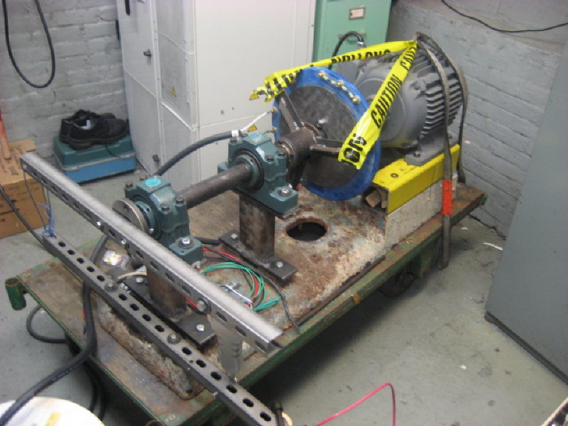
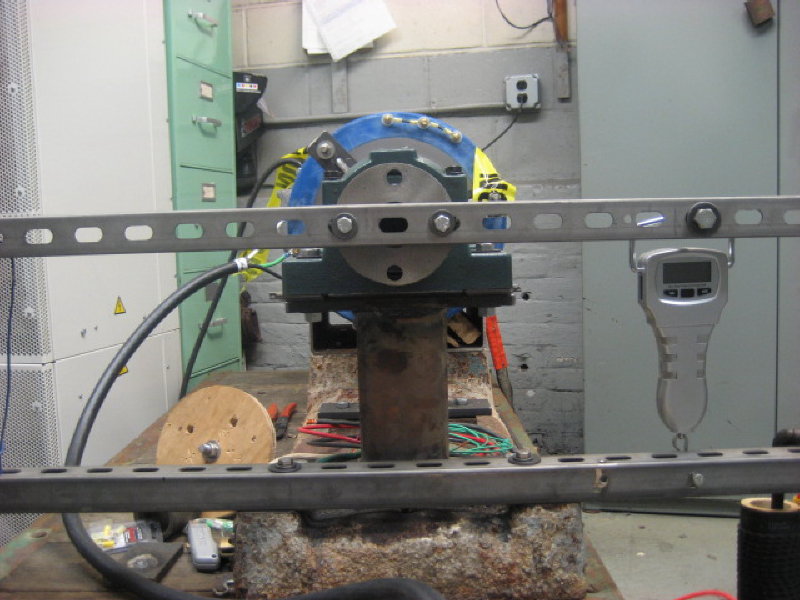
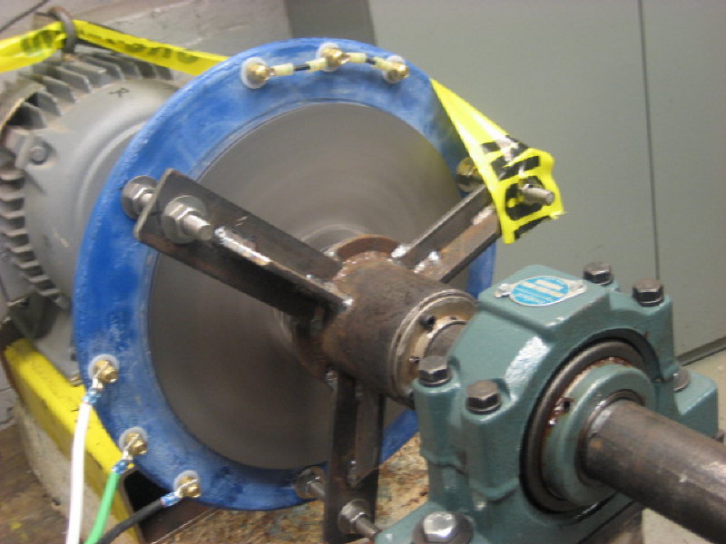
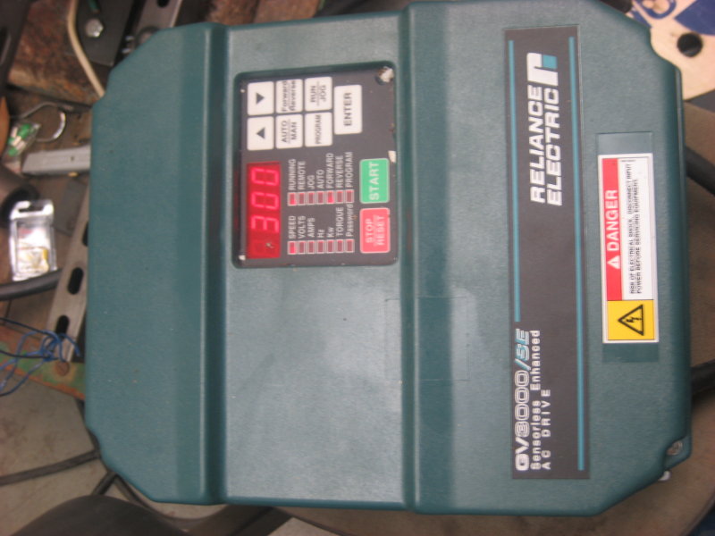
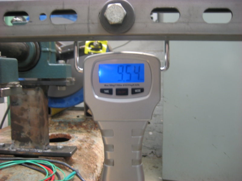
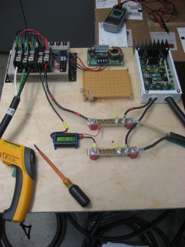
With some technical advice from some guys at work I fabricated a testing platform to gather data.  I'm fortunate to have resources to borrow.   The alternator test bed consists of a low rpm, 3 hp, 3 ph motor powered through a VFD controller.  The power input is measured using a scale mounted 12" across a lever arm.  To eliminate any trig math and angle measurements, the lever arm is on the rotational force center line and the scale is perpendicular to the lever arm.


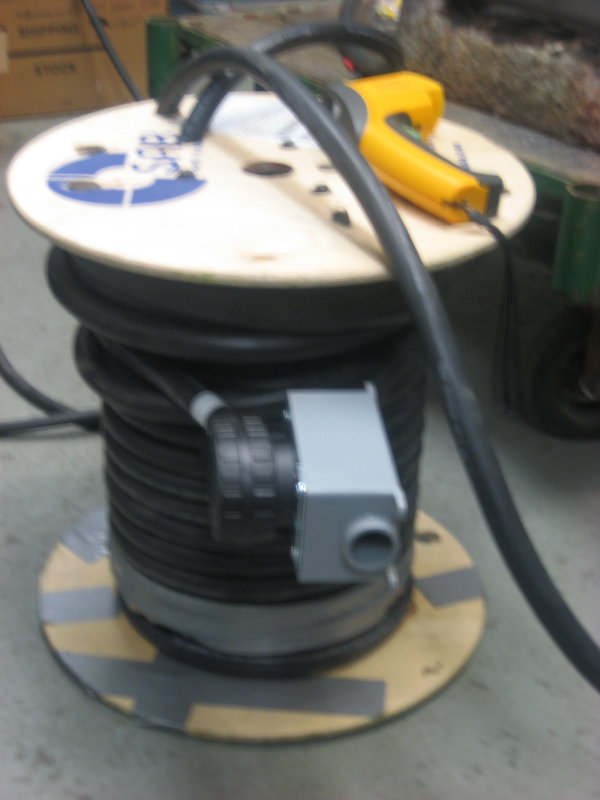
To reproduce actual conditions, the stator is wired with 120' of 6 AWG between the rectifier blocks.  The plug is at 80', which will correspond with the base of the tower.


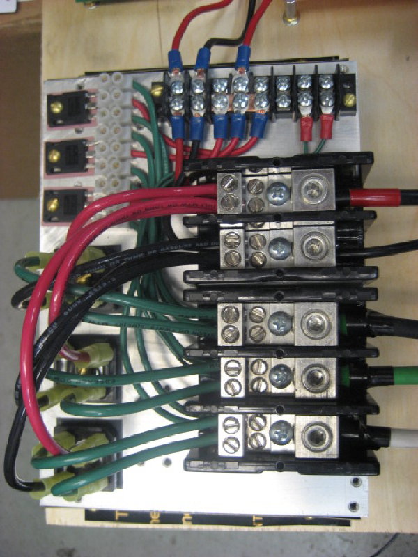
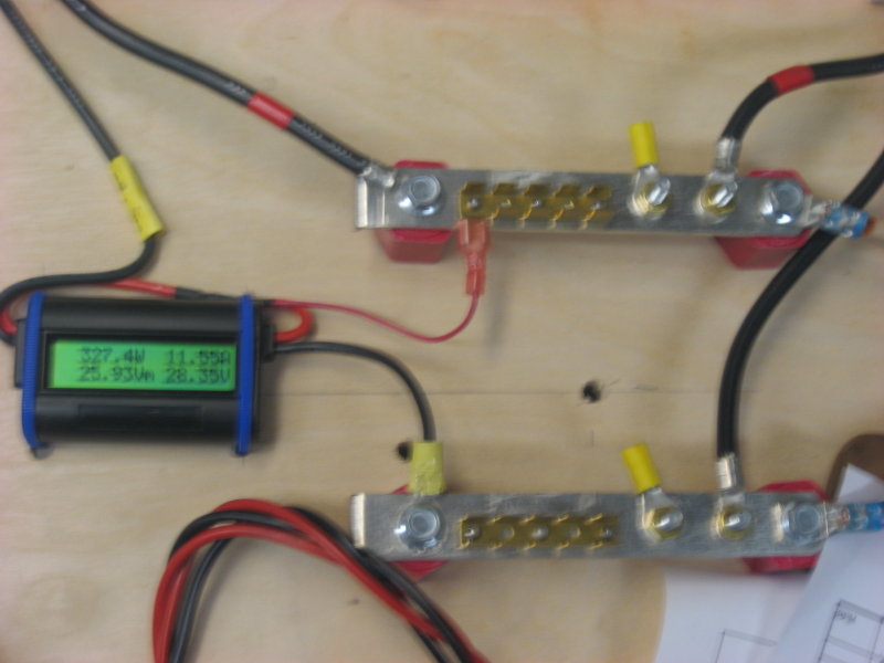
The rectifier and terminal blocks are mounted on a heat sink acquired at Forcefield.  There are two sets of rectifiers, main and boost.


The DC-DC converter is "off the shelf" from Zahn Electronics.  In trying to make it work for a wind turbine application, first I replaced the 0-100%  pwm driver chip with 0 to 50% maximum pwm chip.  There is a turn pot on the PCB for output boost voltage set point.  This allows for boost cut-in speed adjustment (since the pwm is 50% max) and how quickly the output watts increase while boosting.    With the boost voltage set all the up it will easily increase the output to 200 watts at 180 rpm.  Decrease the boost set point below the battery voltage and wattage output does not occur until the alternator achieves battery voltage.  


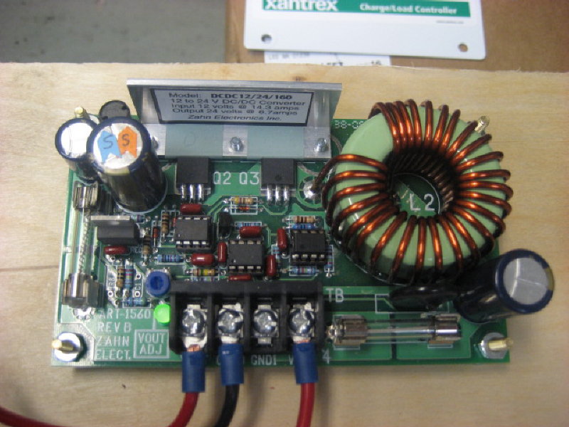
I have more investigation to do on how this boost converter will work.   My concerns are that boost wattage output in going to change considerable as battery voltage change. (It controls to a voltage output.)  For example, if I set the converter to load match the boost properly at 26v (float) and the batteries drop to 24v (LVL), is the wattage output of the boost going increase too much and cause a slow speed stall.  Also I'm currently studying/playing with a microcontroller, may have to "hack" control of that turn pot voltage and try my hand at mppt; Or maybe place a mosfet on the boost converter output to take control that way.


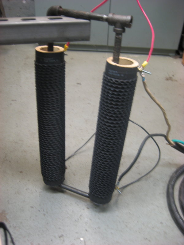
Two one ohm 1000 watt resistors in parallel are used for a dump load.  At 30 volts these should be able to handle 60 amps wired parallel.  Zantrex C60 is the diversion controller.   The controller is a little oversized, but I have dreams of a larger turbine in the future, now control portion will be ready.


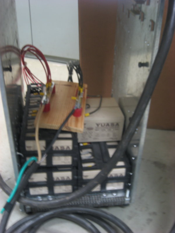
I was able to obtain an obsolete UPS.  It was used as a power backup on a DCS. What a treasure trove of parts.   The buss bars, standoffs, batteries, and nice flexible 6 awg wire are some of the parts put to immediate use.  Also there is a beautiful heat sink (about 25% larger then one in the photo), rectifiers, and circuit breakers are some of the other useful parts.


Here are some initial test results.  I used a meter labeled true rms to measure acv.  Below are the open voltage characteristics of the alternator


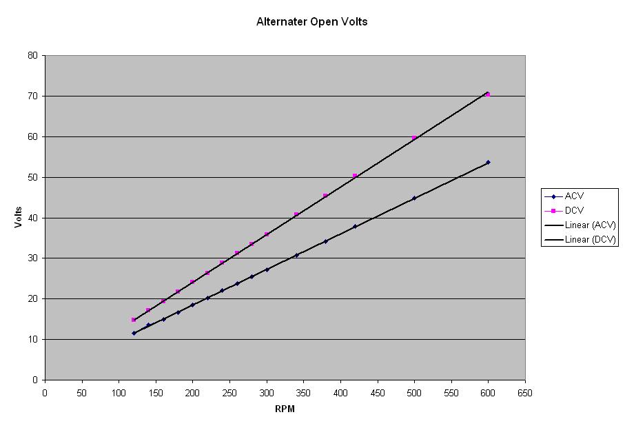
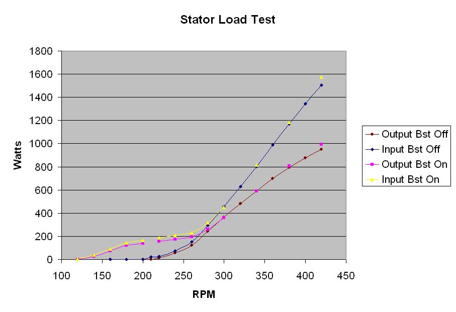
Now with the alternator loaded.  The graph is a little busy since I also superimposed the boost while on and off on the same page.   I plan on doing another series of tests with the boost not set as aggressive.   The alternator efficiencies, at first look, seem to be too good to be true.  This first round of test was completed in a short time and the stator had not heated up that much.   Later, I ran the alternator continuously at 380 rpm.  Initially, the output was 810 watts with a stator temperature of 120 F.  After 15 minutes, the output dropped to 720 watts and the stator temperature increased to 180 F.


Ok,  I'm doing all this because it is fun and to learn.  But also, so I can build a rotor properly matched to the alternator.    As of now,  I'm thinking of carving a 2.6 meter diameter rotor designed for a 6.0 TSR.  Please let me know if this is reasonable for the information collected thus far, or of some other data to collect.  All comments welcome concerning this project.  


Thanks


Boondocker

« Last Edit: June 10, 2007, 04:08:19 PM by (unknown) »

Flux

  • Super Hero Member Plus
  • *******
  • Posts: 6275
Re: Alternator Testing
« Reply #1 on: June 10, 2007, 12:55:59 PM »
This looks good. What is the load? Is it a nominal 24v battery held constant with the charge controller?


Would be interesting to actually measure the output at the alternator to see what loss is in the cable.


Your curves are much as I would expect, the no load waveform is a bit off a sine wave but that doesn't matter at all.


Without the converter your load curve seems to have a bit of a toe at the start, some machines do that. It may also be due to the battery being nominal at the start, then being clamped by the charge control at a higher voltage.


The boost converter looks as though it will do the job, but you say it has a voltage feedback and that is not ideal. If you match it with a nominal battery voltage it will not be ideal as the battery volts comes up, but when the battery is well up you are not in need of ideal conditions. Make it work best when the battery is low.


Probably your choice of prop is sensible but I haven't checked any figures. Efficiency is higher than usual as a result of your higher cut in speed. If you subtract the cable loss, that alternator is doing well.


Like your test rig.


Flux

« Last Edit: June 10, 2007, 12:55:59 PM by Flux »

jimovonz

  • Sr. Member
  • ****
  • Posts: 339
Re: Alternator Testing
« Reply #2 on: June 10, 2007, 02:07:48 PM »
Great job. Thats a lot of effort your putting in there, but I'm sure it will pay off. What an impressive test rig!

I think that a 2.9m prop would be a better match. I have graphed the power curve vs RPM for a 2.6m and 2.9m prop with TSR 6 and a Cp of 0.35:


I think that this is a better match for your 'Input Bst On' curve.

I'd like to comment further but have run out of time - I'll post again later...

« Last Edit: June 10, 2007, 02:07:48 PM by jimovonz »

Boondocker

  • Full Member
  • ***
  • Posts: 193
Re: Alternator Testing
« Reply #3 on: June 10, 2007, 04:19:08 PM »
Flux,


The charge controller went into bulk mode when turned on.  Bulk voltage was set at 28 vdc.  The charge controller did hold a constant voltage once bulk voltage was reached.  Then the controller started to dump the excess.  A noticeable hum occurs when this happens.  


I did measure VAC at the alternator and the terminal block.  Next time I'll try clamping the AC wire with a meter to get AC amps.  Using amps after rectification here are estimated line losses.


« Last Edit: June 10, 2007, 04:19:08 PM by Boondocker »

s4w2099

  • Full Member
  • ***
  • Posts: 234
Re: Alternator Testing
« Reply #4 on: June 10, 2007, 04:49:45 PM »
Hey man Ive been looking for terminal blocks like those that you have in your rectifiers (the black ones in to rightmost part of the picture).


Where did you got those?

« Last Edit: June 10, 2007, 04:49:45 PM by s4w2099 »

Boondocker

  • Full Member
  • ***
  • Posts: 193
Re: Alternator Testing
« Reply #5 on: June 10, 2007, 06:13:59 PM »
McMaster Carr

High-Amp Distribution Blocks & Bars  on page 718
« Last Edit: June 10, 2007, 06:13:59 PM by Boondocker »

willib

  • SuperHero Member
  • ******
  • Posts: 2414
  • Country: us
Re: Alternator Testing
« Reply #6 on: June 10, 2007, 06:47:03 PM »
crap Dude that nice :)

in the shot of the load resistors , how large are they?

cant tell ..
« Last Edit: June 10, 2007, 06:47:03 PM by willib »
Carpe Ventum (Seize the Wind)

Boondocker

  • Full Member
  • ***
  • Posts: 193
Re: Alternator Testing
« Reply #7 on: June 10, 2007, 06:59:06 PM »
They are approximately 15" long.
« Last Edit: June 10, 2007, 06:59:06 PM by Boondocker »

Flux

  • Super Hero Member Plus
  • *******
  • Posts: 6275
Re: Alternator Testing
« Reply #8 on: June 11, 2007, 01:35:59 AM »
Thanks, that makes sense. The toe in the un-boosted load curve will partly be due to the battery voltage rising to 28v before being clamped.


Your figures for line loss are probably reasonable, I don't think I can calculate it from the ac drop figures and dc current. If you have a way of measuring the resistance of the line you can do it from V^2/R for each wire and multiply by three. If your meter is rms ac then it should work ok.


It looks as though you will be near 70% at the alternator at 1kW out so you should be safe at 1kW rating. With typical wind loading you can probably go to 1.5kW and still be reasonably safe but I would stick to 1kW.


That and Jimovonz curves makes me think that if you are not desperately concerned with silence you could run at 2.9m as he suggests. It would even take 3m with tsr raised to nearer nominal 7.


My props always seem to want to run slower than theory suggests in higher winds so if you want to stick to tsr6 then you may need to keep to about 2.8.


Flux

« Last Edit: June 11, 2007, 01:35:59 AM by Flux »

luv2weld

  • Sr. Member
  • ****
  • Posts: 308
Re: Alternator Testing
« Reply #9 on: June 11, 2007, 08:53:38 AM »
I am intimidated and flabbergasted by the test rig and all the devices!!!!

For a poor boy living in the woods, all this stuff is almost beyond comprehension.

However, you have gone to a lot of trouble to get accurate test figures to

ignore one thing that caught my eye. In picture number 9, you show your cable on

a spool. Won't the induction effect the test figures???? OK, it might be only

a tiny amount. But since you have gone to such great lengths to get accurate

data, let's go all the way!!!!


Ralph

« Last Edit: June 11, 2007, 08:53:38 AM by luv2weld »
The best way to "kill time" is to work it to death!

Flux

  • Super Hero Member Plus
  • *******
  • Posts: 6275
Re: Alternator Testing
« Reply #10 on: June 11, 2007, 09:09:33 AM »
The cable coiled up is not a problem. The instantaneous sum of the currents in a 3phase line is zero so there will be no induction to worry about.


If the cable loss was very high then resistance rise could have been an issue, but the cable losses are not high enough to raise the temperature much.


Flux

« Last Edit: June 11, 2007, 09:09:33 AM by Flux »

Boondocker

  • Full Member
  • ***
  • Posts: 193
Re: Alternator Testing
« Reply #11 on: June 11, 2007, 07:16:14 PM »
Flux, Jimovonz,


Wow, 2.8 to 3.0 meters, did not expect that high of a recommendation.  I would prefer to keep the machine more docile and the noise level down.  Never been around a wind turbine before, so have no idea the sound blades turning TSR 7 would be like.   So I'm considering 2.8 meters at TSR 6.


Thanks for sharing your experience.


Boondocker

« Last Edit: June 11, 2007, 07:16:14 PM by Boondocker »

jimovonz

  • Sr. Member
  • ****
  • Posts: 339
Re: Alternator Testing
« Reply #12 on: June 11, 2007, 09:49:43 PM »
I'd be careful, if the power input required by your alt is more than the power your blades can provide at a given rpm, then the blades will slow. The system will slow until equilibrium is reached between power available(blades) and power required(alt). If all points on the power available curve are below the power required curve then the your blades will remain stalled at cutin. You have measured the power required by the alt vs RPM and have estimated the power available from a given set of blades. As it stands, based on the information you have, 2.8m doesn't quite make the required power. I realise that its theoretical at this stage but unless you are happy to introduce more resistance to better match the alt or use a buck converter to regulate the load it pays to go a tad larger on blade size rather than smaller. As far as noise goes, a TSR of 6 means the same tip speed regardless of diameter. I don't think noise will be an issue at all for a 3m TSR 6 turbine that furls at some reasonable speed.
« Last Edit: June 11, 2007, 09:49:43 PM by jimovonz »

Flux

  • Super Hero Member Plus
  • *******
  • Posts: 6275
Re: Alternator Testing
« Reply #13 on: June 12, 2007, 01:04:00 AM »
I agree that 2.6m may show some signs of stall, but it will not be bad. It will not be dragged down like most machines here.


My worry with all these things with no form of mechanical shutdown (can't remember if you have a way) is that when you make the blades big enough to avoid any form of stall you reach a situation where shorting the alternator may not guarantee stopping it in any wind condition. I am sure that it would perform well with 3m and if furled correctly would be perfectly safe on load, but if something happened I am not certain that it would be possible to brake it to a stop under severe conditions.


I think the 2.6m may be a safer long term bet and even if it meant adding a bit of resistance to keep it out of stall it would not matter.


Noise seems to be a relative thing, the conventional stall loaded machines are quiet with the full load tsr coming down to a bit under 5.


Tsr 6 running at 6 is not exactly silent in higher winds, but would probably be considered so by the owners of many commercial machines. When tsr goes over the nominal design figure then things start to become noisy and you approach the helicopter noises at tsr 9 or so in high winds. Much depends on the blade shape and profile, these things matter little at below design tsr.


If you use an appropriate offset then you could always start with slightly larger blades and cut back if necessary but if you cut back you may have to reduce tail weight(on the other hand you may not as the same power will come at a higher wind speed)


Flux

« Last Edit: June 12, 2007, 01:04:00 AM by Flux »

luv2weld

  • Sr. Member
  • ****
  • Posts: 308
Re: Alternator Testing
« Reply #14 on: June 12, 2007, 09:41:38 AM »
Thanks, Flux. I wasn't sure, but thought I'd ask.

I'm probably not even smart enough to be dangerous!!:}


Ralph

« Last Edit: June 12, 2007, 09:41:38 AM by luv2weld »
The best way to "kill time" is to work it to death!

SamoaPower

  • Sr. Member
  • ****
  • Posts: 417
Re: Alternator Testing
« Reply #15 on: June 12, 2007, 03:59:13 PM »
I notice an IR thermometer in your photos. Have you measured the stator temperature at a coil at, say a sustained output of 1 kW or so? It would probably need to run at sustained power for ten minutes of so to stabilize.


I think you could probably add 40-50C to that to get an idea of the internal coil core temperature. This is mainly because of the casting technique.


Just curious.


Congratulations on the best mechanical test setup I've seen yet.

« Last Edit: June 12, 2007, 03:59:13 PM by SamoaPower »

Boondocker

  • Full Member
  • ***
  • Posts: 193
Re: Alternator Testing
« Reply #16 on: June 12, 2007, 05:16:39 PM »
Thanks, I admire your coil technique post.


The temperature of the stator is definitely warmer located over a coil; that is where temperature was measured when I kept the speed at 380 rpm.  The stator is cast out of vinyl ester with ATH.  


I've briefly have had the output at 1500 watts then after about a minute the drive kicked out, overload error.   Only did one temperature measurement, 155 F.


Could try to perform a continuous load test at 1000 watts.  The magnet wire is rated for 200C.   So if the temperature goes above 150C abort the trial to save the stator from damage?   I realize there are no guarantees however, would like to discover a failure on the ground.

« Last Edit: June 12, 2007, 05:16:39 PM by Boondocker »

Boondocker

  • Full Member
  • ***
  • Posts: 193
Re: Alternator Testing
« Reply #17 on: June 12, 2007, 06:43:28 PM »
Flux, Jimovonz


I've been postponing welding the offset  until the blade size had been determined.  


I'm coming up with a 3 meter rotor furling in a 10 ms wind will keep the input limited to near 1.2 kw.  Guess/estimating the blade cp will be down around .25 and the tsr increased to 7 at this stage.  Does this seem reasonable?


Boondocker

« Last Edit: June 12, 2007, 06:43:28 PM by Boondocker »

SamoaPower

  • Sr. Member
  • ****
  • Posts: 417
Re: Alternator Testing
« Reply #18 on: June 15, 2007, 03:06:36 PM »
Yes, thats the idea. It seems you have the capability, with that test setup, to predetermine what a safe power level would be before sticking it in the air.


You can then set your furling to stay well below that level although I wouldn't trust furling to do the whole job. Virtually all of the stator failures I've read about here have used furling tails.


I prefer variable pitch and/or controlled yaw. In addition, I would employ some sort of electronic power limiting for insurance.


Please let us know your temperature test results.

« Last Edit: June 15, 2007, 03:06:36 PM by SamoaPower »

SparWeb

  • Global Moderator
  • Super Hero Member Plus
  • *****
  • Posts: 5452
  • Country: ca
    • Wind Turbine Project Field Notes
Re: Alternator Testing
« Reply #19 on: June 20, 2007, 11:18:11 PM »
Boondocker,

Nice test set-up.  You must have seen all the things I did wrong in my tests and fixed them!

Be careful making assumptions about Cp - it's a slippery number, and depends on a lot of things that are both in and out of your control.  It also varies with speed and relative load, so it is not conservative (structurally speaking) to assume a low value of Cp.


What kind of blade construction are you planning?  Wood?  Fiberglass?  Pitch-controlled?  These things all affect Cp and how it varies over the range of prop speeds.


I'm sure you'll find an excellent solution, if you apply the resourcefulness you have in your alternator tests!

« Last Edit: June 20, 2007, 11:18:11 PM by SparWeb »
No one believes the theory except the one who developed it. Everyone believes the experiment except the one who ran it.
System spec: 135w BP multicrystalline panels, Xantrex C40, DIY 10ft (3m) diameter wind turbine, Tri-Star TS60, 800AH x 24V AGM Battery, Xantrex SW4024
www.sparweb.ca

Boondocker

  • Full Member
  • ***
  • Posts: 193
Re: Alternator Testing
« Reply #20 on: June 23, 2007, 06:17:53 PM »
Steve,


Yes, I did see your test rig and it inspired me to simplify the moment arm angle so the static calculations were straight forward.  Nice tower, starting to think about that phase.


For the blades I'm laminating some quarter sawed spruce lumber together.  

« Last Edit: June 23, 2007, 06:17:53 PM by Boondocker »

SparWeb

  • Global Moderator
  • Super Hero Member Plus
  • *****
  • Posts: 5452
  • Country: ca
    • Wind Turbine Project Field Notes
Re: Alternator Testing
« Reply #21 on: June 25, 2007, 12:14:27 PM »
My workshop never smelled better than it did after sawing through the 4 cedar blades...  You have much to look forward to!

« Last Edit: June 25, 2007, 12:14:27 PM by SparWeb »
No one believes the theory except the one who developed it. Everyone believes the experiment except the one who ran it.
System spec: 135w BP multicrystalline panels, Xantrex C40, DIY 10ft (3m) diameter wind turbine, Tri-Star TS60, 800AH x 24V AGM Battery, Xantrex SW4024
www.sparweb.ca