Author Topic: LiFePO4  (Read 18621 times)

0 Members and 1 Guest are viewing this topic.

commanda

  • Hero Member
  • *****
  • Posts: 731
LiFePO4
« on: August 26, 2009, 07:17:52 AM »
These turned up today.


8 x 90 AHr Thundersky Lithium Iron Phosphate (LiFePO4).  


Manufacturers website here: http://www.thunder-sky.com/products_en.asp


Here I have configured them in 2p4s, for a nominal 12.8 volt pack at 180 AHrs.  Cost to my door was $1405 Aussie dollars.


Dimensions are 490mm x 145mm x 230mm, and weight approx 25.6 Kg.


The manufacturer rates these at 3000 cycles for 70% DoD.  Almost 10 years on a daily discharge cycle. If one uses the lead-acid principle of never more than 50%, they should just about last forever.


Next step is to finish the physical hookup of the control electronics, which will be detailed in the next installment.


Amanda

« Last Edit: August 26, 2009, 07:17:52 AM by (unknown) »

DamonHD

  • Administrator
  • Super Hero Member Plus
  • *****
  • Posts: 4125
  • Country: gb
    • Earth Notes
Re: LiFePO4
« Reply #1 on: August 26, 2009, 05:06:37 AM »
Oh, droooooooooooooooooooooooooool!


Interested to hear what you say about maximum DoD.


Now I'd just like a simple solar controller / BMS for them then I'd swap out my current tiny off-grid 12V 40Ah gel SLA.


Could then permanently tun my main server off-grid.


Rgds


Damon

« Last Edit: August 26, 2009, 05:06:37 AM by DamonHD »
Podcast: https://www.earth.org.uk/SECTION_podcast.html

@DamonHD@mastodon.social

zap

  • Hero Member
  • *****
  • Posts: 1107
  • There's an app for that
Re: LiFePO4
« Reply #2 on: August 26, 2009, 07:11:09 AM »
I agree... drool drool drool

Although the $1450AUD leaves my mouth a little dry.  So maybe around $1212US.. ouch
« Last Edit: August 26, 2009, 07:11:09 AM by zap »

dnix71

  • SuperHero Member
  • ******
  • Posts: 2513
Re: LiFePO4
« Reply #3 on: August 26, 2009, 04:01:03 PM »
Yum. What maintenance is required? Do you have to water them once a month?


If they last as long as predicted they will be much less expensive than Pb in the long run.

« Last Edit: August 26, 2009, 04:01:03 PM by dnix71 »

scottsAI

  • Hero Member
  • *****
  • Posts: 884
Re: LiFePO4
« Reply #4 on: August 26, 2009, 07:26:48 PM »
My comments are not about your decision to use LiFePO4.


Glad you took the challenge, to test and report the benefits and detriments of  LiFePO4


My study of LiFePO4 VS Pb:

Fe: Last forever

Pb: Golf cart and Forklift claim 5 to 8 years.


Fe: Store at any SOC

Pb: Must store charged or damage results. Dry Pb store 10+ years. (New)


Fe: $1200 for 12v @ 180ah

Pb: $140 for 12v @ 225ah. Or 9x cost difference.

(6 to 7) x 9 = 54 to 63 years, including interest: forever.


Fe: 70% charging efficiency

Pb: 91% @ 81% SOC to zero at 100% SOC. (not linear, maybe 50% efficient at 95% SOC)


Study Goal: 3 day Battery backup of 60ah/day load.

Fe: To charge this battery while supplying the load requires more than 60ah to be charging into the battery. To Recovery in two days per backup day requires charging of 90ah per day or 90/0.7=129ah source. Lets assume 5 full sun/hr/day. 129/5 = 25.7a solar charging. Most solar panels peak at 17v x 25.7a = 437w solar panel.

Pb: same conditions. 90/0.91 = 99ah source /5 = 19.8a x 17v = 337w solar panel.

At $4/watt solar panel, Fe battery will cost another $400 for the solar panel. A significant cost delta.

Most RE homes will have a backup generator. Pb requires the use of this generator to equalizing charge the battery (unlikely the solar panel will do it), twice to 6 times a year. The Fe system does not require the generator... Further the Pb, must be fully charged (90-95% SOF) each month (or more often). The above listed solar panel should be able to fully charge the battery yet it will take some days after the bulk charge is replaced, if this does not happen then the generator will be needed to protect Pb battery.


Others details about Fe: electrolyte must be replaced every 7-10 years. Not so with Pb.

Pb: Charging and discharging must be controlled for good battery life. Not so with Fe.

Both Fe and Pb must be watered for full battery capacity. Pb may be damaged if not kept watered. Fe only looses capacity until water is added.


Both systems have pluses and minuses, please look into them and decide for yourself.

New to RE, the Fe systems upfront cost is too high.


Have fun,

Scott.

« Last Edit: August 26, 2009, 07:26:48 PM by scottsAI »

Ungrounded Lightning Rod

  • SuperHero Member
  • ******
  • Posts: 2865
Re: LiFePO4
« Reply #5 on: August 26, 2009, 07:32:52 PM »
70% efficiency?  Adding water?


Are you talking about Lithium Iron Sulfate or Iron Alkaline?

« Last Edit: August 26, 2009, 07:32:52 PM by Ungrounded Lightning Rod »

commanda

  • Hero Member
  • *****
  • Posts: 731
Re: LiFePO4
« Reply #6 on: August 26, 2009, 07:57:39 PM »
LiFePO4 reported charge efficiency better than 95%.


Zero maintenance. Never add water. And what's this about replacing electrolyte?

I think you're getting your chemistries confused.


Amanda

« Last Edit: August 26, 2009, 07:57:39 PM by commanda »

SparWeb

  • Global Moderator
  • Super Hero Member Plus
  • *****
  • Posts: 5452
  • Country: ca
    • Wind Turbine Project Field Notes
Re: LiFePO4
« Reply #7 on: August 26, 2009, 10:15:51 PM »
"25.6 Kg"  

I think think the weight is also a plus on the LiFe cells.  

Something to add to Scott's list.


Can a LiFePO deliver enough current to be used as an engine starting battery?  Or are they all built for deep-cycle?

« Last Edit: August 26, 2009, 10:15:51 PM by SparWeb »
No one believes the theory except the one who developed it. Everyone believes the experiment except the one who ran it.
System spec: 135w BP multicrystalline panels, Xantrex C40, DIY 10ft (3m) diameter wind turbine, Tri-Star TS60, 800AH x 24V AGM Battery, Xantrex SW4024
www.sparweb.ca

scottsAI

  • Hero Member
  • *****
  • Posts: 884
Re: LiFePO4
« Reply #8 on: August 26, 2009, 10:30:42 PM »
by gorge your right.


What I wrote has nothing to do with LiFePO4.


Please ignore my comments.


Scott.

« Last Edit: August 26, 2009, 10:30:42 PM by scottsAI »

zap

  • Hero Member
  • *****
  • Posts: 1107
  • There's an app for that
Re: LiFePO4
« Reply #9 on: August 26, 2009, 11:49:03 PM »
http://www.lifebatt.com/HPSpacks.asp


http://www.yesa.com.cn/goods.asp?id=74


http://headway-cn.en.alibaba.com/product/206234106-50269244/Lithium_Ion_Batteries/12v30Ah_LiFePO4_li
thium_ion_battery_pack_with_petrol_energy_saving_system.html


I've even seen some of the portable jump starters with the LiFePO4 chemistry listed online but you will rarely see prices listed.

« Last Edit: August 26, 2009, 11:49:03 PM by zap »

zap

  • Hero Member
  • *****
  • Posts: 1107
  • There's an app for that
Re: LiFePO4
« Reply #10 on: August 26, 2009, 11:56:32 PM »
« Last Edit: August 26, 2009, 11:56:32 PM by zap »

electrak

  • Jr. Member
  • **
  • Posts: 62
Re: LiFePO4
« Reply #11 on: August 28, 2009, 04:34:59 AM »
I'm in the process or putting together a small engine start LiFePO4 pack, I'm getting parts and whatnot, check out the older diaries, I have one spring holder made sofar, and can short it for better than 20 amps, what my meter will read, so 3, 2300mah in parralal should do better then 60-70 amps with should start a motorcycle, hopefully
« Last Edit: August 28, 2009, 04:34:59 AM by electrak »

SparWeb

  • Global Moderator
  • Super Hero Member Plus
  • *****
  • Posts: 5452
  • Country: ca
    • Wind Turbine Project Field Notes
Re: LiFePO4
« Reply #12 on: August 29, 2009, 09:54:50 AM »
Thanks guys,

Expensive but may soon be practical in weight-sensitive applications (like airplanes?).
« Last Edit: August 29, 2009, 09:54:50 AM by SparWeb »
No one believes the theory except the one who developed it. Everyone believes the experiment except the one who ran it.
System spec: 135w BP multicrystalline panels, Xantrex C40, DIY 10ft (3m) diameter wind turbine, Tri-Star TS60, 800AH x 24V AGM Battery, Xantrex SW4024
www.sparweb.ca

SamoaPower

  • Sr. Member
  • ****
  • Posts: 417
Re: LiFePO4
« Reply #13 on: August 29, 2009, 02:11:35 PM »
Here's an interesting quote from a all-battery.com email ad.


"Comparing Amp-hour ratings between PbA and LiFePO4 is tough. Peukert's exponent explains the capacity expected from a PbA cell at given discharge currents. The equation is:


I^x * t = Ah


I = current discharged


x = exponent


t = time


Ah = total Ah's


Most PbA cells have a Peukert's exponent rating between 1.3 and 1.6. Good PbA cells have an exponent the gets closer to 1.15. We can't assign this exponent to LiFePO4 because of chemistry differences, but an approximation of the Peukert's exponent for comparison would be 1.05 for LiFePO4. As an example, a 20Ah LiFePO4 cell will produce approximately as much or more power as a 50Ah PbA cell at the same rated voltage."

« Last Edit: August 29, 2009, 02:11:35 PM by SamoaPower »

commanda

  • Hero Member
  • *****
  • Posts: 731
Re: LiFePO4
« Reply #14 on: September 06, 2009, 02:00:41 PM »
This weekend, I got the control electronics finished off enough to start putting some charge into the batteries from my lone 120 watt solar panel and a 6 amp smart charger.
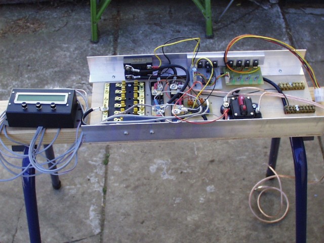


Black box on the left with the lcd and 3 pushbuttons is my amp-hour meter. Was working previously on my SLA batteries, now won't boot. Will investigate later.


Moving to the right is a fuse block for connecting the loads, 2 x current shunts, the tiny little pcb is the amplifiers for the current shunts, a 70 amp circuit breaker, and terminal blocks for the incoming power. On the aluminium angle, one on each side, are a pair of 30 volt, 100 amp, solid state relays. One is the low voltage disconnect, the other is the bulk charge switch.


The 2 pcb's on the aluminium angle is the BMS. Board on the right is the per-cell circuitry, while the board on the left is the control circuitry.


The per-cell cct'y consists of a shunt regulator set at 3.65 volts, and a low-voltage detect set at 2.7 volts. Each of these feeds a common buss, and is opto-isolated. The green led comes on with the shunt regulator.


On the control board, the 3 TO-220 devices are:

one to power the low voltage disconnect SSR,

one to power the bulk charge SSR,

and the one in the middle is a constant current source for the final equalisation charge.  The constant current source is in parallel with the bulk charge SSR.


The low voltage signal drives a flip-flop, so once triggered the load stays off until manually reset. The RC network which makes the flip-flop start in reset state needs a bigger capacitor, and silly me forgot a pin header on the pcb for the reset switch.


Pdf's of all the circuitry coming in the next instalment.


Amanda

« Last Edit: September 06, 2009, 02:00:41 PM by commanda »

DamonHD

  • Administrator
  • Super Hero Member Plus
  • *****
  • Posts: 4125
  • Country: gb
    • Earth Notes
Re: LiFePO4
« Reply #15 on: September 06, 2009, 02:25:03 PM »
]]]More undignified drool on my part![[[
« Last Edit: September 06, 2009, 02:25:03 PM by DamonHD »
Podcast: https://www.earth.org.uk/SECTION_podcast.html

@DamonHD@mastodon.social

commanda

  • Hero Member
  • *****
  • Posts: 731
Re: LiFePO4
« Reply #16 on: September 07, 2009, 08:43:30 PM »
And here's the functional block diagram of the control circuitry as a pdf.


Amanda

« Last Edit: September 07, 2009, 08:43:30 PM by commanda »

SamoaPower

  • Sr. Member
  • ****
  • Posts: 417
Re: LiFePO4
« Reply #17 on: September 09, 2009, 03:57:18 PM »
Nice going Amanda.


I'm curious as to how much balancing current your individual cell shunt regulators allow. Of course, this effects how quickly the balancing operation will happen and I would think that with a 180Ah battery, it could take a while, depending on amount of imbalance and the current level.


I'm somewhat concerned about my system, since with intermittent charge sources (solar and wind), they may not reach a balanced state soon enough. The A123 cells have a reputation of holding balance fairly well after 10-15 break-in cycles so it may not be an issue.


I took a slightly different approach to balancer shunts in the BMS. Rather than linear shunt regulators, I use voltage detectors with 70mV hysteresis driving FET switches with 1 ohm loads. This puts most of the heat into resistors rather than the active devices for hopefully, better reliability. This results in peak balancing currents of 3.6A.


I've had my 56Ah A123 pack on line for about two weeks now, but do the balancing with a separate balancing charger toward end of charge since my BMS isn't finished yet (still laying out the PCB).


I'd be interested in hearing your experiences as you go along. Good luck with it.


Bill

« Last Edit: September 09, 2009, 03:57:18 PM by SamoaPower »

commanda

  • Hero Member
  • *****
  • Posts: 731
Re: LiFePO4
« Reply #18 on: September 09, 2009, 05:54:46 PM »
From my experience with the 40 AHr pack in my scooter, the cells stay very well balanced on their own. On the scooter, the equalisation/finishing current is limited to about 1/2 amp, and with 16 cells in series, it's typically about 3 minutes from first cell reaching full charge, to last cell reaching full charge.


With this 180 AHr pack, I've again limited the finishing current to 1/2 amp. On the scooter, once all cells are charged, the charger switches off. With the 180, it continues forever at the finishing current, or until you start discharging the pack. This gives a dissipation in the shunt regulators of about 7 watts.


Amanda

« Last Edit: September 09, 2009, 05:54:46 PM by commanda »

SamoaPower

  • Sr. Member
  • ****
  • Posts: 417
Re: LiFePO4
« Reply #19 on: September 11, 2009, 01:57:28 PM »
Thanks for the info Amanda.


What are your charge sources going to be when installed in your caravan? I assume that when underway, you will use the engine alternator. When stationary, will you use solar and/or wind?


I assume that your "all shunts on" signal is used to turn off the charge sources via the SSR leaving the 1/2A finishing current, so I guess that you won't be using wind since you make no mention of diversion loading.


I haven't seen any information about long term effects of floating LiFe at, or near their full-charge voltage. Since their current acceptance is quite low at full charge, I'm assuming it's not a problem. What do you think?

« Last Edit: September 11, 2009, 01:57:28 PM by SamoaPower »

commanda

  • Hero Member
  • *****
  • Posts: 731
Re: LiFePO4
« Reply #20 on: September 11, 2009, 03:24:46 PM »
Samoa,


Caravan will be in a fixed location, not worrying about trying to charge from the vehicle alternator.


Initially it will be solar only. Need at least one more panel yet. Will add a wind turbine later.


Actually, it's "any shunt on" which turns off the bulk charge SSR, leaving just the 1/2 amp current source. Looking at my circuit, "all shunts on" turns off the 1/2 amp current source as well. Correction to what I wrote previously.


Any diversion controller would need to be across the source, not the battery. A pwm controller would be ideal, or the dump load controller I've already built and described on here previously, although the switching time constant would need to be much shorter, or non existent.


Amanda

« Last Edit: September 11, 2009, 03:24:46 PM by commanda »

SamoaPower

  • Sr. Member
  • ****
  • Posts: 417
Re: LiFePO4
« Reply #21 on: September 11, 2009, 05:42:49 PM »
Okay, I understand.


You can achieve about 1-2% more charge if the battery is left at the constant-voltage, full-charge level (3.6-3.7V/cell) for some period of time after the last shunt kicks in. This could be determined by a minimum current (? - into the battery) detection or perhaps, be left indefinately. Hence, my question of your opinion about possible long-term effects of float at full voltage, which I would like to use.


Diversion controller = Dump load controller, in my opinion. If you're going to consider a wind source, I think you need one of these.


"Any diversion controller would need to be across the source, not the battery."


I don't understand this comment since, in most systems, the wind source AND/OR solar source are connected directly to the battery with the dump load switched in parallel with the "whole shoot'n match" (is this an Americanism?) to maintain a certain maximum battery voltage by diverting excess current from the source(s) and provide sufficient load to the wind turbine. I've always used diversion control (dump load), even on solar only systems, because I want to make use of the extra energy, beyond battery charging, for other purposes.


I've included a PWM diversion controller in my BMS using a TL494 and a bank of FETs - pretty simple. When nature is really cooperating, I get a full battery charge as well as some air conditioning via the diversion controller.


Your thoughts?


« Last Edit: September 11, 2009, 05:42:49 PM by SamoaPower »

commanda

  • Hero Member
  • *****
  • Posts: 731
Re: LiFePO4
« Reply #22 on: September 11, 2009, 05:53:23 PM »
All shunts low switches off the charge current completely, after a time delay set by an RC network. Currently 4M7 and 10uF. I think this is too short, based on having it running for the last week. The last cell in the pack is always at a lower voltage than the rest. Might need a switch across the capacitor to disable it for a while at least, until I can get the whole pack fully charged.


The diversion controller needs to be across the source, because of the constant current charge regime. Otherwise the shunt regulators would have to take the full current supplied.


Amanda

« Last Edit: September 11, 2009, 05:53:23 PM by commanda »

SamoaPower

  • Sr. Member
  • ****
  • Posts: 417
Re: LiFePO4
« Reply #23 on: September 11, 2009, 06:21:31 PM »
WOW, that was a quick response!


What you are seeing may be simply an effect of new cells that haven't been "broken in" yet. I don't know if those behave the same way as the A123 cells or not, but mine need about 10-15 full cycles to stabilize, although it may be a result of incomplete balancing on previous cycles as you elude to.


Re: Diversion controller.

I'm not sure I understand your comment since the diversion (dump) load would dump most of the current around the shunt regulators. This assumes a low dump load resistance. In my case, I'm using 0.2 Ohm 1 kW. This is PWM controlled.

« Last Edit: September 11, 2009, 06:21:31 PM by SamoaPower »

commanda

  • Hero Member
  • *****
  • Posts: 731
Re: LiFePO4
« Reply #24 on: September 11, 2009, 07:32:16 PM »
Yeah, it's Saturday morning, and we're in reasonably close time zones.


The diversion controller thing. The setpoint voltage on the diversion controller would have to very closely match the sum of the shunt regulators.  There is also an effect of the dynamic resistance of the shunt regulators, and also temperature effects.


If the diversion controller is set just slightly higher than the sum of the shunt regulators, and charging it with a constant current source, it will never come on.  Set it just slightly lower, and at least one cell will never charge properly.


Also, with the constant current source, the diversion controller will never be able to control a wind turbine.


Put the diversion controller across the source, and set the turn on voltage about a volt higher than the battery voltage. The one volt difference will be soaked up by the current source, and with a low enough voltage drop to keep heat generation minimal. Now the diversion controller can dump all that the wind turbine is producing.


Amanda

« Last Edit: September 11, 2009, 07:32:16 PM by commanda »

SamoaPower

  • Sr. Member
  • ****
  • Posts: 417
Re: LiFePO4
« Reply #25 on: September 12, 2009, 01:57:47 PM »
I've reset to full width.


I'm still trying to understand the advantages of using the constant-current source for the balancing and finish charge. As far as the battery is concerned, it doesn't care if the source is constant-current or not since its acceptance will determine the actual current in any case as long as the voltage is held constant (second part of CCCV).


So, it appears the only reason for the current source is to act as a current limiter for the linear shunts which is certainly valid if you are using linear shunt regulators. It's one reason I tried to avoid linear regulators.


I've noticed that a cell is still accepting substantial current when it first reaches 3.6V so I don't think I would want to externally limit that current to lengthen out the balancing/finishing time since my source could go away at any time.


FYI here's the circuit for what I've elected to use for balancing shunts. It has been tested and functions well for the job.


The TL431 acts as a comparator with positive feedback via the 200k which sets hysteresis at about 70mV. It mimics PWM (sort of) as the cell voltage oscillates between 3.60 and 3.53V. The FET Rdson is only 4mOhms so it needs little heat sinking at 3.6A. Current limiting is by the 1 Ohm resistor, of course.


The advantages over linear are: little heat in the FET, full source current is available for the balancing/finishing charge, with all switches on it acts as a mini diversion load, and quicker balancing.


Your feedback will be appreciated.

« Last Edit: September 12, 2009, 01:57:47 PM by SamoaPower »

commanda

  • Hero Member
  • *****
  • Posts: 731
Re: LiFePO4
« Reply #26 on: September 12, 2009, 04:50:27 PM »
Samoa,


Minor problems:

the 2N4403 should (may)be replaced with a darlington.

you haven't specified a part number for the Fet. Gate turn on voltage to achieve saturation is critical. Garden variety fet won't work.


Major problem:

the one ohm dump resistor means maximum charge current is limited to 3.6Amps.


This circuit is derived from the case where you charge 4 cells in series as a 12 volt block with an SLA smart charger, which winds back the current as the voltage comes up.


Although aimed at the EV solution, there are some interesting ideas in this thread.

http://www.aeva.asn.au/forums/forum_posts.asp?TID=900&PN=1&SID=9d6c72db775e5e4a1466ffdb32678
abd


And from the pushbike crowd.

http://endless-sphere.com/forums/viewtopic.php?f=14&t=5416


Mine is based on the much earlier version of this last one. They now pwm the bulk charge switch, whereas I use a linear constant current source. Not sure how their method would work with a wind turbine.


Amanda

« Last Edit: September 12, 2009, 04:50:27 PM by commanda »

SamoaPower

  • Sr. Member
  • ****
  • Posts: 417
Re: LiFePO4
« Reply #27 on: September 12, 2009, 10:50:45 PM »
Thanks for your thoughts Amanda.


"the 2N4403 should (may)be replaced with a darlington."


Not really. The Tl431 has plenty of gain. The 2N4403, which has a beta of about 300, is well saturated at turn on.


"you haven't specified a part number for the Fet. Gate turn on voltage to achieve saturation is critical. Garden variety fet won't work."


Sorry for omitting the P/N. It's a NTD110N02R. Rated typical gate threshold is 1.5V. Gate voltage in this circuit at turn-on is about 3.4V which saturates it well for Id of 3.6A.


"Major problem:

the one ohm dump resistor means maximum charge current is limited to 3.6Amps."


I'm not sure what you mean by this since the bulk charge current (below 3.6V/cell) doesn't flow through the 1 Ohm resistors (all FETs off). Perhaps you mean the balancing charge current AFTER the first balancer has turned on, which is true but is seven times greater than the 0.5A you are using. But remember, the cell current acceptance is decreasing rapidly at this point. Perhaps I didn't make it clear that this is the balancing circuit across each cell (4 used) not a dump load controller for the whole pack. The balancing current (cell discharge) is 3.6A.


I tested this circuit on a 4S1P pack and it balanced the pack very quickly, about 15 seconds from first one on to the last one on. Of course, on the larger 4S24P Pack it'll take longer.


Thanks for the links.


Bill

« Last Edit: September 12, 2009, 10:50:45 PM by SamoaPower »

commanda

  • Hero Member
  • *****
  • Posts: 731
Re: LiFePO4
« Reply #28 on: September 14, 2009, 03:24:54 AM »
Bill,


Bit slow on the uptake sometimes, but I've figured out how yours works.

Once the batteries are full, as the charge current increases up to 3.6 amps, the shunts will turn on full. Any further increase in current beyond 3.6 amps, the voltage will increase proportionally due to the one ohm resistors. So you set the dump load controller to just above 3.6 * 4 = 14.4 volts.


(would have written this 12 hours ago, but the site has been inaccessible for me most of the day).


Amanda

« Last Edit: September 14, 2009, 03:24:54 AM by commanda »

SamoaPower

  • Sr. Member
  • ****
  • Posts: 417
Re: LiFePO4
« Reply #29 on: September 14, 2009, 03:27:54 PM »
Amanda,


Yes, well, we each have our own ways of interpreting circuit operation and describing same. It looks like you pretty much have it.


Yes, the main PWM diversion controller will be set to 14.6V. This will allow a topping off charge to get that extra 1-2% as long as the source current is greater than 3.6A. A cell voltage of 3.65V is no problem for the A123 cells.


Here's the rest of the per cell circuitry - the Low Voltage Cutoff (LVC):


It's similar to the balancer detector but with an off voltage of 2.7V and 300mV hysteresis - back on at 3.0V. I elected to have automatic reset rather than manual so that load surges don't have me running for the reset switch. If the battery is truly down and it recovers to more than 3.0V, it'll simply cycle - still protecting the battery.


The PS2505-4 is four photocouplers in a 16 pin DIP. The four output transistors are in series from the total pack voltage and provide the OR function. This output drives a bank of five NTD110N02R FETS as the load switch in the negative battery line. The RC filter helps protect against load surges.


I hope you don't think I'm trying to hijack your thread. I simply value your feedback so I don't make any stupid mistakes before I finalize the PCB.


Many Thanks.


Bill

« Last Edit: September 14, 2009, 03:27:54 PM by SamoaPower »

commanda

  • Hero Member
  • *****
  • Posts: 731
Re: LiFePO4
« Reply #30 on: September 14, 2009, 03:55:19 PM »
Bill,


For LVC, consider the TC54. It's a low voltage reset chip for a micro. Output pulls low when voltage goes below a set voltage. Could use less components.


For the Thundersky cells, the manufacturer recommends charging to 4.2 volts per cell. Field testing shows a difference of only 1 to 2 % in capacity between 3.65 volts and 4.2 volts.  Tesla motors recently changed their charging regime to decrease the final voltage, in the interests of battery cycle life.  For RE, I think the limiting factor is the typical over-voltage cutout of common inverters, which I believe is usually 15.5 volts.


Amanda

« Last Edit: September 14, 2009, 03:55:19 PM by commanda »

SamoaPower

  • Sr. Member
  • ****
  • Posts: 417
Re: LiFePO4
« Reply #31 on: September 14, 2009, 05:49:30 PM »
Amanda,


Thanks for the suggestion. Yes, I did consider the TC54 but rejected it for a few reasons. You're right, it would take fewer parts but, not being programable is a drawback. Different fixed voltages are available but I have limited access to parts. I also wanted to be able to control the differential.


I agree that using LiFe for RE takes some additional considerations compared to vehicle or RC use. The most significant, in my opinion, is that we're working with variable and intermittent charge sources instead of nice and steady mains chargers. Also, using wind turbines brings up its own set of issues, mainly the need for diversion.


One question I'm still concerned about is any long term effect from floating them often (daily) for a number of hours at their full charge voltage. I haven't found any information about this. I do know that it is recommended that long term storage be at about half charge. However, this doesn't fit for RE use with daily cycles. Any opinion?


We may be breaking new ground here.


Bill

« Last Edit: September 14, 2009, 05:49:30 PM by SamoaPower »

commanda

  • Hero Member
  • *****
  • Posts: 731
Re: LiFePO4
« Reply #32 on: September 15, 2009, 12:51:55 AM »
Bill,


I also have not found any info online about the effects of holding the batteries at their fully charged potential for any length of time.  Considering that the leakage current is minimal once fully charged, and the fact that we are well below the manufacturers recommended full voltage (3.65 vs 4.2 for the TS), I would be inclined not to lose too much sleep over it.


My setup has an RC timer to shut off the charge current once all cells are full. Admittedly, the time constant is too short. Still, with a switch across it to disable it (weekly perhaps ?) I can go either way. Not hard to replace the RC timer with a binary counter and flip-flop to get more realistic times.


Agreed, we are very close to the cutting edge of new technology here. Not many doing it, let alone documenting it.


Amanda

« Last Edit: September 15, 2009, 12:51:55 AM by commanda »