This first comment is a test to see how the pictures look.
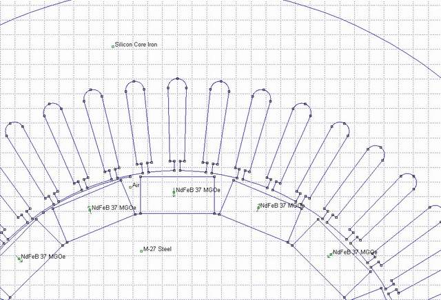
It's the geometry for a 25 hp Baldor with 1" x .5" x 2" mags on the rotor.
Zubbly, I took a look at the picture you posted of this machine before, and took a guess at a couple of numbers. I put the OD of the lamination stack at 11.56", the length of a slot at 1.25" and the slot width at around .25". Hope that's close!
I didn't take the flat parts on the stator OD into consideration.
This simulation is 1" deep if you can imagine it goes to that depth into the page.
The magnets are N37 since the program didn't have N35.
The airgap (ie between the corners of the magnet and the stator) is .040".
If this works as planned, you will be able to click on a picture to see it full size.
We'll see!
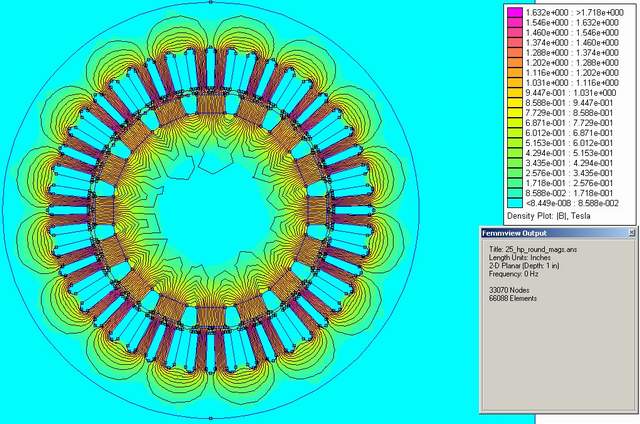
Anyhow, the pic above is with the magnets sitting flat on the rotor, something like Jacques did for his 215 conversion.
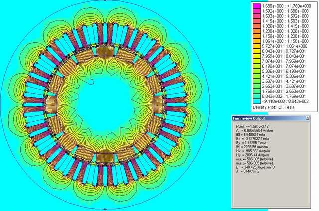
The next pic is the flux. The point in the output box sitting at 1.6T is in the purple section on one of the stator teeth.
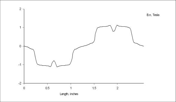
The normal flux plot in the airgap over 2 poles:
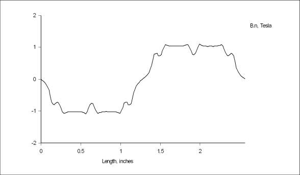
The integral over 1 pole for the flat mags is .8046T
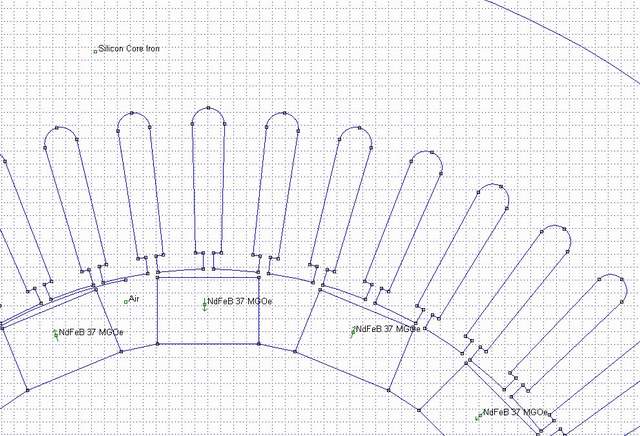
Next for the 1" round magnets. The surface area of a 1" round magnet is about .785 square inches, so I for the simulation I used the .785" for the width and left the simulation depth at 1". I believe this will come close to the effect of using round vs. rectangular mags.
The geometry for the round setup assumes flat spots have been milled into the rotor for the mags to sit on.
The flux density plot:
The normal flux in the airgap over 2 poles:
The integral over 1 pole is .6684T
So all things being equal I would choose the flat magnets (1 x 2 x .5) over the round ones!
If you download a copy of the FEMM program let me know and I'll post the files for this - that way you can open them and play with this on your own PC.
Ted.
