Author Topic: Double the coils or double the magnets (single vs dual rotor)  (Read 4186 times)

0 Members and 1 Guest are viewing this topic.

planetlajord

  • Newbie
  • *
  • Posts: 7
  • Country: ca
Double the coils or double the magnets (single vs dual rotor)
« on: February 24, 2020, 01:57:50 PM »
Sorry if I'm in the wrong section! Learned a TONNE from this board but it's my first time posting.

Just about to start my 3 phase PMA build but I can't seem to find an exact answer to this question or the physics behind it. Would I get more power from more coils on a single rotor PMA or from less (but ticker) coil positions on a dual rotor (opposing magnets) PMA?

Background: I have 24 total cylinder, neo magnets (1.25" diameter, 1" thick with a 0.5" hole) and near endless supply of pre-made street lamp ballast coils (3.25 x 2.5 x 0.75). I realize these aren't ideal shapes or sizes and it wont be an exact science but these are all free and what I have to work with. Initial experiments passing a single magnet over a coil exceeded all expectations.
Blade size will be determined once I know the forces required to rotate the alternator. The use of this will be to directly power water heating elements (to heat a thermal battery water tank in the winter and a pool in the summer). Total or capacity/number of elements will be determined by the end resulting power. I live on a farm on the open prairie in Southeast Saskatchewan Canada with some of the best wind on the continent and a 50' tower.

See diagram:

<blockquote class="imgur-embed-pub" lang="en" data-id="a/VGlMuyc"><a href="//imgur.com/a/VGlMuyc">PMA for Fieldlines discussion[/url]<script async src="//s.imgur.com/min/embed.js" charset="utf-8"></script>

Scenario 1: Large diameter, single rotor
18 coil stater (6 coils per phase) and 24 total magnets on a single rotor (with an apposing steel rotor to focus the magnetic flux)

Scenario 2: small diameter, dual rotor
9 coil position stater (with stacked coils to make a thicker coil, so still 18 in total), with two x12 magnet rotors opposing each other (connected via steel bolts to close the flux loop).

I just need the direction that provides the most raw wattage and highest amperage. Thanks for your input everyone!


MagnetJuice

  • Hero Member
  • *****
  • Posts: 557
  • Country: ca
Re: Double the coils or double the magnets (single vs dual rotor)
« Reply #1 on: February 24, 2020, 02:57:46 PM »
Welcome to Fieldlines,

As you said, those shapes are not ideal. However, if it is all you have, then you have to find a way to work with it.

I can tell you that scenario 2 will give you very little power. The reason for that is that your two stacked coils will be too thick. In that situation, the magnetic flux from magnet to magnet will be minimal.

If you tell us the dimension of the inside hole of the coils, there could be possible to arrange those magnets and coils in a different configuration that will produce more power.

Also, tell us the gauge of the wire in the coil. The wire size determines how much current can safely flow through the coils.

Ed
What can I do TODAY that would make TOMORROW a better world?

planetlajord

  • Newbie
  • *
  • Posts: 7
  • Country: ca
Re: Double the coils or double the magnets (single vs dual rotor)
« Reply #2 on: February 24, 2020, 03:47:50 PM »
Thanks Ed!
I think the diagrams I drew up would help explain this better than my feeble words, got outsmarted on uploading a pic on here when I made the post.

The hole in the coils is 1.25 x 2", they are remarkably similar to the DIY trapezoidal coils I have seen except they are rectangles. They have four leads on them (common, 110v 220v and 277v). I have one that's in rough shape that I can sacrifice. I will cut through it to do a turn count and gauge measurement (pretty small gauge), I'll attach a photo when I get home tonight. Essentially though, one cylinder magnet can fit inside, two side by side is 0.5" too big.

I am not opposed to winding my own coils if there is an optimum shape, turn count, gauge etc. in relation to my cylinder magnets. Any suggestion on how/where to get cheap, bulk magnet wire would be appreciated, all I can find so far in Canada is on Amazon.ca in tiny little roles and outrageously priced at hobby shops. If I do go this direction, I will definitely need help on the coil winding (pretty much ignored that learning up until now because I haven't been able to let go of these seemingly perfect, pre-made coils! haha).

Thanks again!


bigrockcandymountain

  • Hero Member
  • *****
  • Posts: 659
  • Country: ca
Re: Double the coils or double the magnets (single vs dual rotor)
« Reply #3 on: February 24, 2020, 04:57:54 PM »
I am in rural southwestern saskatchewan.  Welcome to fieldlines. 

I believe the thickness of the coils will be the most important measure.  I believe the optimum air gap is a function of magnet thickness. 

  I am no expert on axial flux.  I am firmly a motor conversion follower. 

I hope you get it done and flying.  There is a lot of power in the wind in saskatchewan.

MagnetJuice

  • Hero Member
  • *****
  • Posts: 557
  • Country: ca
Re: Double the coils or double the magnets (single vs dual rotor)
« Reply #4 on: February 24, 2020, 08:17:33 PM »
The holes on those coils are too long for one magnet. It would be better to use two magnets per coil.


With two magnets, there will be some magnetic flux wasted, because power is produced only when the wire is perpendicular to the magnet. The small section at the end of the coils will not produce power because there the wire is parallel to the moving magnet. But using only one magnet will waste too much copper.

With two magnets, you will get more voltage out of each coil. If the wire in those coils is at least 18 Gauge, you should be able to use them, especially if you settle for a higher voltage, like 48 volts.

The alternator will have 12 double magnets and 9 coils with a blank steel rotor on the other side.

Better yet, magnet4less have 1 x 2 x .5 rectangular magnets (Model: NB056-0) very cheap, about $6.50. Can you use round magnets on one rotor and rectangular magnets on the other rotor? Absolutely. It would look funny but it will work perfectly OK. In addition, it will produce a lot more power that with just an empty rotor on one side. As you already said, utilize what you already have.

If the wire in the coils that you have is too thin, you will be better of winding your own coils. If you wind your own, they should be round with the center holes the same diameter as the magnet. The coil thickness should be between .5 and .625.

Here are two sources to buy magnet wire. They both ship to Canada. 15 Gauge will match those magnets for a nice 48-volt alternator. Those are 10 Lbs. spools. Nice price.

https://www.ebay.ca/itm/AWG-15-Copper-Magnet-Wire-H200C-High-Temp-10-lbs/252569441837?hash=item3ace4fd62d:g:MdYAAOxyXWdQ6xcP

https://www.magnet4less.com/essex-magnet-wire-15-awg-gauge-enameled-10lbs

If you need help calculating the number of turns per coil, just ask. Someone here can help you.

Ed
What can I do TODAY that would make TOMORROW a better world?

planetlajord

  • Newbie
  • *
  • Posts: 7
  • Country: ca
Re: Double the coils or double the magnets (single vs dual rotor)
« Reply #5 on: February 25, 2020, 10:21:35 AM »
Wow, thanks! Consider this advice followed! I'm going to split the difference and make two PMAs, one with the free magnets I have (and make new coils) an another with the free ballast coils I have (and purchase the rectangle magnets).

PMA 1: Round magnets - custom round coils
I will order a roll of the wire you recommended and do my own round coils for optimum use of the round magnets. It will be a dual rotor (12 per), 9 coil assembly. Assistance on the turn count for these would be greatly appreciated! What other information/data is required from me to help determine the turn count? Keeping in mind I have strong wind the majority of the time (or so it always seems). I'll be looking for the highest, raw energy to power water heating elements.

PMA 2: Pre-made ballast coils and purchased rectangle magnets
This one I will purchase 24 of the recommended square magnets you suggested as they seem to be MADE for the ballast coils I have. At $6.50 per magnet, I gotta try at least. This will also be a dual rotor (x12 per), 9 coil assembly. If the coils cant take that amount of power I will split it into two single rotor assemblies.

bigrockcandymountain: I also have a couple smaller motor conversions on the go from a washing a machine and a dryer motor using small neo's. I do have several questions in regards to magnet to coil orientation and re-wiring but I suppose there is a more appropriate area to post those. Perhaps one bridge at a time.

PS. I also have x15 other huge, ring magnets but not sure if they are practical for anything. They are 3.5" diameter, 0.625" thick and have a 1" hole in the centre, scary strong.... any thoughts? a HUGE rotor for a VAWT maybe? Break them into quarters to get x60 smaller magnets? Yet another bridge for another time.

Thanks again all!

MagnetJuice

  • Hero Member
  • *****
  • Posts: 557
  • Country: ca
Re: Double the coils or double the magnets (single vs dual rotor)
« Reply #6 on: February 25, 2020, 11:34:05 PM »
PMA 1 - Good idea. Those magnets are somewhat an unconventional shape, but they are powerful. You could build a nice alternator with them.

To be able to calculate the number of turns for the coils, a few things have to be known.

The voltage that you want to produce is important. I know that you want to use it to heat water with heating elements. You will find out soon that using a wind turbine for direct heating is more complicated than using it to charge batteries. If you design it for a 60 volt output, you will be able to use it to charge a bank of 48 volt batteries if connecting it directly to heating elements turns out to be too much trouble for you.

Another thing you need to know is at what RPM you want the turbine to reach your desired voltage.

That will depend mostly on the diameter of your rotor (turbine blades).

I hope that some of the members here can give you guidance in that direction. I have some knowledge in that area but is limited compared to some of the pros here that have built their own machines.

PMA 2 - Hold on ordering the magnets until you know for sure if those ballast coils are suitable.

I noticed that those coils have taps on them. That is interesting; it could be possible to wire the taps in parallel to get more current through them.

Find out the Gauge and the number of turns on those coils. That is a priority.

About those big ring magnets that you have, if they are Neodymium, there is not much you can do with them when it comes to building the type of alternator that we are talking about. They are too big and extremely hard to cut. If they are Ferrite, they will not be powerful enough for an alternator, especially if you cut them in 4 pieces. I plan to buy 4 of those Neo rings. I want to use them to magnetically levitate a VAWT turbine.

Ed
What can I do TODAY that would make TOMORROW a better world?

planetlajord

  • Newbie
  • *
  • Posts: 7
  • Country: ca
Re: Double the coils or double the magnets (single vs dual rotor)
« Reply #7 on: February 27, 2020, 11:21:24 AM »
Pre-made coil information:
outside dimensions: 3-1/8" tall, 2-11/16" wide, 5/8" thick
Inside dimensions: 1-7/8" tall, 1-7/16 wide"

There are 5 total leads (taps): Common, 120, 208, 240, 277. I get by far the highest voltage spike waving a magnet over coil when connected to comm and 277 so I suspect they are in series to obtain higher voltages.

I sawed through one and did a wire count and got approximately 424 wires (plus or minus 5). Unfortunately I do not have a way to measure AWG gauge but they are quite thin. I will invest in a digital caliper.

Do these thinner wires risk over heating?

As for desired RPM, voltage, blade size etc. I am VERY open to suggestions. I have a tall tower and am capable of fabricating quite elaborate and large blades. Based on visual comparison of other DIY rigs (with very similar alternator sizes and configurations), I was expecting to do 3 x 8' blades with fiberglass reinforced laminated ply wood (with steel core) or fibre glass reinforced, carved high density polystyrene (with steel core). I don't even know the slightest to estimate the power or RPM they would produce... so that is as much of a mystery to me as my wife's annoyance of my passion for this project! haha

SO... its a classic chicken and the egg scenario

Do I need to build blades and apparatus first to get real world wind, torque, and rpm data so that I can best optimize the alternator?  Or do I build the best damn alternator with what I got then build the rest of the apparatus to suit the needs of the alternator ?
12677-0

Once again, not a scientist here but will have continued access to a lot of free Neodymium cylinder magnets and pre-made coils. I am comfortable not reaching absolute peak efficiency because I can just keep putting up more and more monsters... I am ok with a V8 on a motorcycle but not ok with a lawnmower engine in my one tonn.

Once again, humbled by the help!

ps. Very inspired by your levitating VAWT idea! I hope you share your progress!


planetlajord

  • Newbie
  • *
  • Posts: 7
  • Country: ca
Re: Double the coils or double the magnets (single vs dual rotor)
« Reply #8 on: February 27, 2020, 11:23:25 AM »
12678-0

planetlajord

  • Newbie
  • *
  • Posts: 7
  • Country: ca
Re: Double the coils or double the magnets (single vs dual rotor)
« Reply #9 on: February 27, 2020, 11:24:19 AM »
12679-012680-1

MagnetJuice

  • Hero Member
  • *****
  • Posts: 557
  • Country: ca
Re: Double the coils or double the magnets (single vs dual rotor)
« Reply #10 on: February 28, 2020, 11:35:30 PM »
Thank you for the photos and the details, that helps a lot.

After doing some analysis of your pictures and numbers, this is what I deducted:

The wire in those coils seem to be 20 Gauge. By separating the wires at the taps, one of those coils can be divided into 4 individual coils.
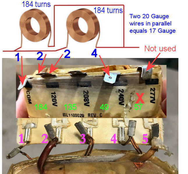


These are my estimates of the number of turns and resistance of the individual coils if the wire is 20 gauge:

Coil 1, between taps 1 and 2 has 184 turns. Measures 1.42 ohms.
Coil 2, between taps 2 and 3 has 135 turns. Measures 1.05 ohms.
Coil 3, between taps 3 and 4 has 49 turns. Measures .38 ohms.
Coil 4, between taps 4 and 5 has 57 turns. Measures .44 ohms.

Coils 2 and 3 in series equals 184 turns. That is the same as coil 1. GREAT!

Coil 1 can be wired in parallel with 2 and 3 to make one coil and reduce the resistance to .71 ohms. When those two 20 gauge coils are wired in parallel, it is the same as having one coil wound with 17 gauge wire. So if my estimates are correct, those coils can be used.

17 Gauge wire is good for 19 amps. That will give you the capability to output over 900 watts at 48 volts from the alternator. 24 of those 2 x 1 x .5 Neo magnets can produce that much.

If you decide to go with 120 volts AC output by wiring the 2 coils in series, 20 Gauge wire is good for 11 amps. That is good for over 1 Kw alternator, not bad.

You can verify all this by measuring the resistance of the coils and verify the gauge with a caliper. You can measure resistance from tap to tap without having to separate the coils.

Measuring low resistance with a multimeter can be problematic, but the resistances here are not that low. Just make sure that before you measure, short the leads, note the resistance of the leads, and subtract that from the coil resistance.

If my calculations are correct, an alternator with 9 of those 184 turn coils (1 and 2 +3) and 2 magnet rotors with 12 magnets each of the 2 x 1 x .5, will output around 1 Kw.

I calculated output voltages at different RPM and they are as follows:

At 370 RPM with the 2 coils in parallel = 121 Volts AC RMS
At 185 RPM with the 2 coils in series = 121 Volts AC RMS
At 130 RPM with the 2 coils in parallel = 58 Volts DC

Keep in mind that these are open voltages without a load.

You asked if you build the alternator first or the rotor blades. Since you already have all the parts to build the alternator, you build that first. Then calculate the power output and RPM of the alternator. Once you know that, you try to find the best size blades to match that alternator.

I am hoping that some of the experts here jump in and offer some guidance as to the size of the blades once we estimate the parameters of the alternator.

Here is a useful table:
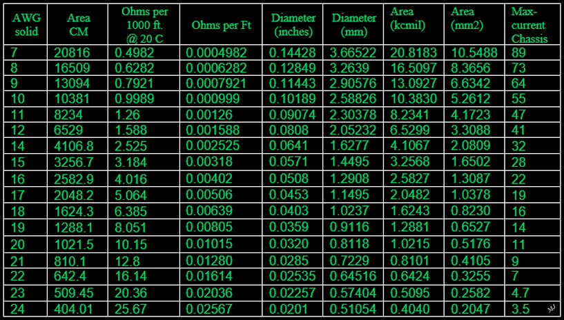
12681-1

Your wife seem to be typical. Ladies are more concerned with results rather than the details. When she will be able to use the warm pool in late September, she will come around.  ;)

Ed
« Last Edit: February 29, 2020, 12:41:51 PM by MagnetJuice »
What can I do TODAY that would make TOMORROW a better world?

planetlajord

  • Newbie
  • *
  • Posts: 7
  • Country: ca
Re: Double the coils or double the magnets (single vs dual rotor)
« Reply #11 on: March 02, 2020, 04:33:50 PM »
Wow, that's amazing, thank you for dedicating this time and being so thorough! I am sure you are experienced in this phenomenon but the more I am learning, the more questions I have!

So just to summarize:

Scenario one: parallel coil 1 with coil 2 and coil 3 to make "20 AWG" equivilent to "17 AWG" ; resulting in 19 amps, 900 watts at 48 volts AC
Scenario two: Keeping it 20 gauge and series the two coils (which two?) resulting in 11 amps, 1,000 watts, at 120 volts ac.

I suppose there is a trade off in power between the two, are there any advantages/disadvantages I should consider between them? Is one scenario more likely to produce better power for water heating elements? Also, I may need more help in understanding the series vs parallel process, also not sure why coil 2 was double labled and pointed to twice in the diagram, is 3 being skipped  in that diagram as well?

I am curious to understand why all the coils wouldn't be utilized, if the copper is already there, why not use it?

Thank you so much for this help Ed, already light years ahead of where I was.

As for the wife, I'm sure she'd rather see me finish the basement; however, she is glad this is my hobby, when I could be out drinking, gambling or playing video games! Ha... nothing against those hobbies BTW.

MagnetJuice

  • Hero Member
  • *****
  • Posts: 557
  • Country: ca
Re: Double the coils or double the magnets (single vs dual rotor)
« Reply #12 on: March 02, 2020, 10:44:49 PM »
Keep in mind that all the calculations I made are based on assumptions. We cannot move forward until you know for sure the gauge of the wire and the resistance of the coils. I don’t know if you have a digital multimeter and a caliper. If you live close to Regina, Canadian Tire sells both. One thing I don’t like about Canadian Tire is that their regular prices are way too high. I only buy there when the items are on sale, their sale prices are 50 to 75% off.

Another choice is to buy a meter from Amazon.ca. Whatever multimeter you buy should be True-RMS. I use FLUKE meters, because I bought them long ago. Now you can buy good True-RMS multimeters for less than $50. If you need help selecting a meter let me know and I can recommend one.

The reason that you cannot use all the wire in the coil is that if it is 20 gauge, the resistance of 424 turns will be very high, especially when you have to connect 3 of those coils in series per phase for the alternator. That will triple the resistance of one coil. An alternator with high resistance waste too much power heating itself. It can burn too.

If you intend to use this turbine to heat water, the heating elements come in many different voltages. I think that 48 or 120 Volts would be best. There is no difference in power output between 60 volts at 18 amps and 120 volts at 9 amps. Both will give you 1,080 watts.

For 120 volts from the alternator, the 2 coils have to be in series to keep the RPM of the turbine at a reasonable speed (not too high). For 48 volts, the 2 coils have to be in parallel for better current handling. I think that designing for 48 volts would be a better choice, just in case that you later decide to use the turbine to charge batteries.

Here is the 2 coils that I am referring to. I hope this is a better explanation.

There are 5 terminals on this coil. Terminals 2, 3, and 4 have two wires each coming out of the coil. To separate the 2 coils that you need, you have to cut terminal 2. After you cut it, you will have 2 wires coming from terminal 2. The wires from terminal 1 and 2 is your first coil. The other wire from terminal 2 to terminal 4 is your other coil. Leave the 2 wires from terminal 3 connected and make sure that they are connected really good. You don’t need to cut anything else. Terminal 5 is not used.


The reason that you can use those 2 coils in parallel is because they have the same number of turns, 184 if my estimates are correct. The only way to find out for sure if those 2 coils have the same number of turns is by measuring their resistance. If they have the same resistance, we are OK. As I said before, I estimate the resistance of the 2 coils we need at 1.42 ohms each.

Here is a short explanation of how an alternator produces power.

This is very basic knowledge; maybe you know this already.

Output power is dependent on 3 things. Magnet size, turns of wire in the coils and speed. A coil with 20 turns will produce twice the voltage of a coil with 10 turns. An alternator spinning at 100 RPM will produce twice the power as an alternator spinning at 50 RPM. Another thing is that the wire size (gauge) of your coils has to be able to conduct all the current without getting very hot. A simple definition of power in this case is volts multiplied by amps. In the example above 60 volts multiplied by 18 amps equals 1,080 watts.

Ed
What can I do TODAY that would make TOMORROW a better world?

Ungrounded Lightning Rod

  • SuperHero Member
  • ******
  • Posts: 2865
Re: Double the coils or double the magnets (single vs dual rotor)
« Reply #13 on: March 10, 2020, 07:55:43 PM »
(Attachment Link)
FYI, back to that diagram in your Feb 24 posting:  At the same RPM, and with the same current limit in the coils (due to heating) Scenario 1 would produce twice the power of scenario 2.  Here's why:

Scenarios 1 and 2 have about the same flux.  Scenario 1 has half the magnetic thickness and half the gap of scenario 2 (along with passive "salient pole" flux guides to keep the field within the coi's opening).  The mag thickness and gap thickness pretty much cancel out.

Scenarios 1 and 2 have the same number of turns being cut by the same amount of flux, because in scenario 2 the coils are stacked.

But scenario 1 has twice the number of poles cutting each coil per turn of the shaft.  The rate of change of the flux in the hole / cutting the coils on the way in and out is twice as high so the voltage is twice as high.  (The drag on the shaft is twice as strong because the lever arm is twice as long, so you pull twice the HP from the shaft and energy is conserved.)

Scenario 1 is effectively the same as running scenario 2 at twice the RPM.

(Actually, scenario 1 is a little bit better yet - because the coils get more cooling with all sides exposed, so you can run them at slightly higher current with the same amount of resistive loss.)