Author Topic: Making a slip ring connector  (Read 23721 times)

0 Members and 1 Guest are viewing this topic.

Chuck

  • Jr. Member
  • **
  • Posts: 77
Making a slip ring connector
« on: July 18, 2003, 11:22:02 AM »
I've never liked the idea of letting a wire dangle directly from a wind generator, twisting as the wind shifts direction and requiring occasional untangling. A few weeks ago I purchased some old wincharger tower stubs at an auction ($5 each). These both had ring assemblys on them and one had the original (siezed) generator in place. They gave me an opportunity to seriously look into slip ring designs and how to get them to work in a homebrewed system.


The following is a quick look at how I used readily available plumbing parts to make a usable slip ring and brush assembly.


The parts:


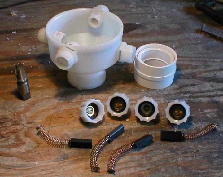
Most of the parts are shown above. All were purchased at a local hardware store. What is missing above, and shown in a photo further down, is a sheet of copper and some electrical connectors. Missing from all photos is a small brush spring holder made from a cardboard tampon inserter.


The Brush Assembly:


The largest part is a 1 1/4" (ID) to 3" (ID) plastic pipe adapter. This has holes drilled into it and threaded to accept four smaller threaded pipe adapters (not sure of the size right now, but I think it may be 3/8"ID by 3/4"ID) which are screwed into it. These are offset by ~3/4", in pairs, to match the placement of the rings.


Each of these four adapters has a cap for each end. The inner cap is drilled out so as to fit the brush that will go through it. The larger, outside cap is drilled to size for a brass screw. Above you see the larger cap already assembled with brass screw, brass washer and rubber washer already in place.


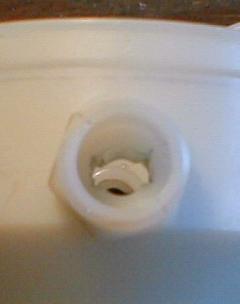
The Brushes were the largest I could find at the hardware store. The smaller part of the 4 adapters is chiseled out (1/4" chisel) to fit the brush size and shape as shown below. This can be laborious, but using the brushes themselves to size the holes is a great help. The carbon on the brushes rubs of on the high spots of the slot showing you where to trim down more.


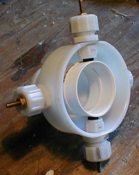
The following shows how the pieces fit together to hold the brushes against the ring assembly. It is preferable to have some kind of holder for the springs, which will flop about in the larger cap area. I used 5/8" sections of a super sized tampax applicator. These applicators consist of two concentric cardboard tubes. Using both extended allows the rather long springs to be easily placed in the caps and they slide together as the cap is tightened. The larger tube also fits snugly in the rubber washer and guides the spring end of the brush into strong, direct contact with the brass washer and screw end for a good connection. Without the spring holders, the brushes don't have a secure and consistant push against the rings.


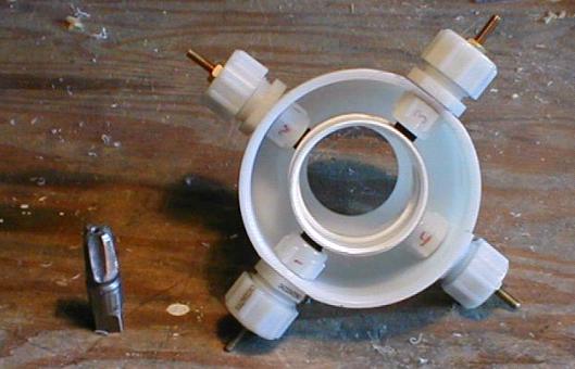
The alternator/generator leads attach to the screws on the brush assembly. The opposing brushes should be linked together so two brushes carry each side of the circuit. For a 3 phase assembly, you would need to add a ring and offset another set of brushes.


The ring assembly:


The ring assembly starts out with a plastic plumbing joint. I used a 2" ID piece and eventually glued a smaller joint inside it to reduce the inside diameter to closer fit my tower mast.


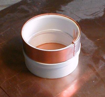
It's not necessary, but I turned slots into the outside of the joint piece so there would be a plastic ridge between the two rings. These slots and the smaller inside joint are visible in the top photo.


For the rings themselves I cut 3/4" strips of copper sheet which I wrapped around the joint piece and then glued to the joint. I used a hand saw to cut a slot in each side to accept the ends of the copper sheet. I left about an inch extra length on each side of the copper strip after pulling it tight through the slots. I then cut shorter copper strips and bent them in half fitting them over the existing extra lengths of ring inside the joint piece. These become the attachment points for the wire going down the tower. The upper attachment strips are longer and to the full length of the joint plus an inch or two. I filed down the inner ridge of the joint where this longer strip goes through. Inserting the smaller joint exerts a clamping force on these strips and some epoxy makes it permanent.


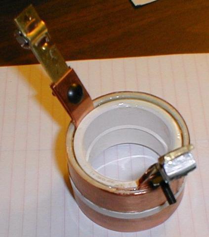
On the ends of these strips I attached some brass electrical connectors. This adds rigidity to the strips so they don't short out against the tower or an opposing ring. I angled these out for the same reason.


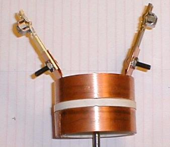
This whole excersize was to to get a good connection for my peculiar wind turbine setup. The top (smaller) end of the brush assembly attaches to my wind generator. The ring assembly attaches to the mast of my tower, a Rohn 25G. I think this basic concept can be used all sorts of places for an inexpensive rotating power takeoff with just enough modification to fit the existing application.

« Last Edit: July 18, 2003, 11:22:02 AM by (unknown) »

DanB

  • Global Moderator
  • SuperHero Member
  • *****
  • Posts: 2151
  • Country: us
    • otherpower.com
Re: Making a slip ring connector
« Reply #1 on: July 18, 2003, 12:09:29 PM »
Thats nice Chuck!  Probably not an issue, but my concern would just be... the possibility of high current overheating it.  Probably not an issue, especially at higher voltages, but it would be interesting to bench test the assembly with the highest possible current you'd expect from the turbine for a while and see if things heat up at all.  I get surprised sometimes how even big chunks of carbon get pretty hot under fairly low current.


Someone on this board suggested using the brushes from Automobile starter motors... they seem like some kind of copper/graphite substance (or something)  -but they take higher current.


I like my "dangling wire" :-)   but it might be a problem if I had to leave it for an extended period of time.


Thanks for the cool pictures and good ideas!  Be fun to see how it works... bet it works fine.

« Last Edit: July 18, 2003, 12:09:29 PM by DanB »
If I ever figure out what's in the box then maybe I can think outside of it.

Chuck

  • Jr. Member
  • **
  • Posts: 77
Re: Making a slip ring connector
« Reply #2 on: July 18, 2003, 01:35:26 PM »
Dan,


Thanks for the comments.


Yes, high current is an issue I'm very concerned with, especially with plastic brush holders (I've seen plastic brush holders melted in motors). That's one reason I went with 2 brushes for each side of the circuit. It would be easy enough to make it 3 or 4 per side if need be, or just find higher capacity brushes like you suggest.


I have a 24 volt system and don't expect this generator to put out much over 20 or 30 amps, about 10 - 15 amps per brush. Still might be too much, I don't know, but I should find out soon.


Chuck

« Last Edit: July 18, 2003, 01:35:26 PM by Chuck »

TomW

  • Super Hero Member Plus
  • *******
  • Posts: 5130
  • Country: us
How much resistance?
« Reply #3 on: July 18, 2003, 02:08:33 PM »
Nice writeup, Chuck.


One question comes to mind first. How much resistance across the commutator / brush assembly?


I ask because the loss through that setup might be considerable if the resistance is much at all.


Those I^2 R losses are hard to beat.


Just with round numbers if its .1 ohm per brush pair you will see 90 watts lost in each pair of brushes at 30 amps output.  [.1*[30*30]] or .1 * 900.


Just curious.


Cheers.


TomW

« Last Edit: July 18, 2003, 02:08:33 PM by TomW »

wdyasq

  • Hero Member
  • *****
  • Posts: 1324
Re: Making a slip ring connector
« Reply #4 on: July 18, 2003, 05:37:38 PM »
Of course it is easier to suggest improvements to someone's inspitation than to come up with something yourself... First, Good job and fine looking craftsmanship.


I think one could use a short section of "hard copper pipe" or even just one of the little solder connectors for the slip rings.  I believe there would be less to fail.


Ron

« Last Edit: July 18, 2003, 05:37:38 PM by wdyasq »
"I like the Honey, but kill the bees"

Chuck

  • Jr. Member
  • **
  • Posts: 77
Re: Making a slip ring connector
« Reply #5 on: July 21, 2003, 10:51:52 AM »
Thanks Tom and Ron for the comments,


Tom, I'll have to try to measure the resistance on the whole assembly and see what it is.


Interesting thing about that formula, it doesn't hurt you as much at higher voltages.


For 12v:


  1. amps - loose 10 watts out of 120 or 12%.
  2. amps - loose 40 watts out of 240 or 16%.
  3. amps - loose 90 watts out of 360 or 25%.


For 24v:


  1. amps - loose 10 watts out of 240 or 4%.
  2. amps - loose 40 watts out of 480 or 8%.
  3. amps - loose 90 watts out of 720 or 12.5%.


For 48v:


  1. amps - loose 10 watts out of 480 or 2%.
  2. amps - loose 40 watts out of 960 or 4%.
  3. amps - loose 90 watts out of 1440 or 6%


It makes one seriously consider higher voltage systems.


Ron, Yes, the copper pipe is a better solution in some ways. I originally did build a prototype that used copper pipe, but I found that I couldn't get it in the size I needed for this setup from local sources. Even 2" was difficult to come by and I needed an odd size above that.


Winchargers relied on rings that weren't appreciably thicker than the copper sheeting I used, and that was for a 6 volt system. The only real difference is the joint, which I don't like. But sometimes you compromise to get something done.


« Last Edit: July 21, 2003, 10:51:52 AM by Chuck »

Jerry

  • Hero Member
  • *****
  • Posts: 1519
Re: Making a slip ring connector
« Reply #6 on: August 05, 2003, 10:36:17 PM »
Hi Guys

I've been flying gennys now for about 5 years without slip rings. Just send the wire down the mast. I've never had a twist problem.


If its good enough for Hugh its good enough for me.

Anyway I don't want to loose any power I've tryed so hard to get.


I'll be putting up a genny this winter with most of its wire exposed. This will have about 30 feet of wire visable. This will be a good chance to see what hapens to wire without slip rings. May take some befor and after pics. It will be a good study.


              JK TAS Jerry

« Last Edit: August 05, 2003, 10:36:17 PM by Jerry »

Chuck

  • Jr. Member
  • **
  • Posts: 77
revisions
« Reply #7 on: September 15, 2003, 12:52:39 PM »
After a 70mph storm and a failure of the slip rings shown above, I have a few revisions for this design to deal with higher amperage. The failure was due to sparking near the ring joint, resulting in a melting of the ring and the plastic brush holder melting onto the brush, siezing it in place.


  1. Use solid copper rings if possible. The use of copper sheet may be OK if you can solder the joint and sand it smooth with the curve of the ring. Size can be a problem getting appropriate copper pipe for the rings.
  2. A metal sleeve between the plastic holder and the brush will keep changes to the plastic from affecting the brush's ability to move. Assuming things get too hot. A thin copper sheet might suffice for this.
  3. Larger wires on the brushes should reduce the resistance and thus the heat buildup in the brushes. This unit was passing over 20 amps when it failed.


Chuck
« Last Edit: September 15, 2003, 12:52:39 PM by Chuck »