Ho progettato una turbina Banki Crossflow sperimentale, dimensionata per una caduta di 50' = 15 metri e una portata d'acqua di 0,33 cfs = 9,4 litri al sec. Potenza idrica = 1380 watt, Potenza elettrica = 621 Watt (se il rendimento totale dell'impianto picoHydro è di 0,45).
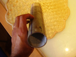
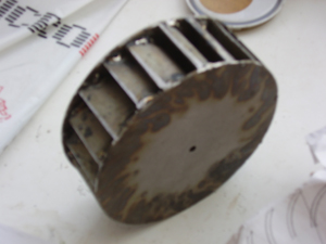
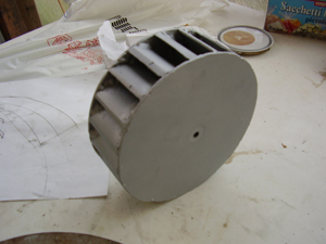
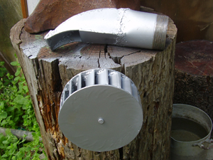
La turbina è costituita da 20 palette ricavate da un tubo dal diametro interno di 2", racchiuse in due dischi di acciaio inox dello spessore di 3 mm, con un diametro di 6,1" = 15,5 cm.
Qui sotto ci sono i disegni e i calcoli effettuati per il progetto:
Plans for the realization of one turbine Banki Cross-Flow .
I have planned a turbine Banki Crossflow experiences them, determine the proportions for one fallen of 50' = 15 meters and a water capacity of 0,33 cfs = 9,4 liters sec. Power water = 1380watt, Power electrical = 621watt (if the rendering total of the system picoHydro is of 0,45).
The turbine is constituted from 20 blade from a tube from the inner diameter of 2", enclosed in two stainless steel discs of the thickness of 3 mm., with one diameter of 6,1" = 15,5 cm.
Here under there are the designs and the calculations carry out you for the plan:
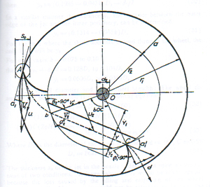
CALCOLI
H = altezza caduta = 50' = 15 metri.
Portata acqua = 0,33 cfs = 9,4 litri al secondo
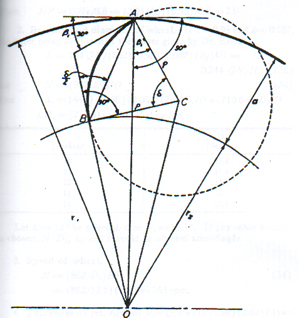
p= raggio paletta = 1" = 2,54 cm.;
r1 = raggio del disco = (p/0,326) = 3,06" = 7,7 cm;
D1 = diametro disco laterale = r1*2 = 3,06*2 = 6,1" = 15,5 cm;
a = (0,17*D1) = 0,17*6,1" = 1,037" = 2,65 cm;
r2 = (r1 - a) = 3,06" - 1,037" = 2,023" = 5,14 cm;
(L*D1) = (210,6 * Portata acqua / H ½ ) = 210,6 * 0,33 / 7' = 9,93";
L = 9,93"(L*D1) = 9,93"/6,1" = 1,62";
L = 1,62" + 25%(compensazione perdita spessore pallette) = 2" = 5,1 cm.;
N = velocità turbina = (862/D1)*H ½ = (862/6,1")*7 = 990 rpm;
altezza teorica paletta = 73,28° di un tubo del diametro interno di 2" = 1,456" = 3,7 cm;
circonferenza esterna di un tubo di 2" (con spessore 0,118" = 3 mm.) = 17,835 cm;
Il disco è stato suddiviso per venti palette = 360°/20 = 18°
CALCULATIONS:
H = Head = 50' = 15 m.
Capacity water = 0,33 cfs = 9,4 liters to the second
p= radius blade = 1" = 2,54 cm.;
r1 = radius of disc = (p/0,326) = 3,06" = 7,7 cm;
D1 = diameter lateral disc = r1*2 = 3,06*2 = 6.1" = 15,5 cm;
a = (0,17*D1) = 0,17*6,1" = 1,037" = 2,65 cm;
r2 = (r1 - a) = 3,06" - 1,037" = 2,023" = 5,14 cm;
(L*D1) = (210,6 * Capacity water/H ½) = 210,6 * 0,33/7' = 9,93";
L = 9,93"
(L*D1) = 9,93" /6,1" = 1,62";
L = 1,62" + 25% (compensation loss thickness grape shots) = 2" = 5.1 cm.;
N = speed turbine = (862/D1) *H ½ = (862/6,1") *7 = 990 rpm;
theoretical height blade = 73,28° of a tube of the inner diameter of 2" = 1,456" = 3,7 cm;
external circumference of a tube of 2" (with thickness 0,118" = 3 milimeter) = 17,835 cm;
The disc is subdivided for twenty shovels = 360°/20 = 18° .
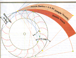
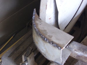
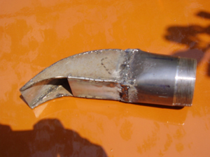
Qui sotto è riportato un iniettore che provvede all'immissione dell'acqua nella turbina a 16 °.
Nel mio caso ho scelto un triplo Nozze.
Here under an injector is brought back that supplies to the breaking in of the water in the turbine to 16 °.
In my case I have chosen triple a Nozzle.
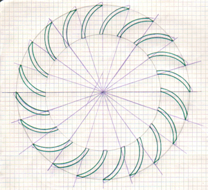
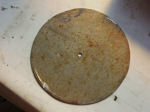
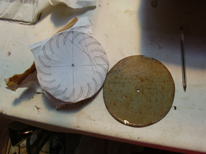
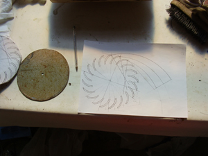
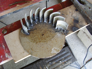
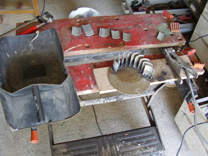
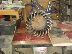
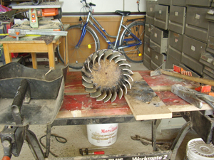
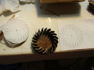
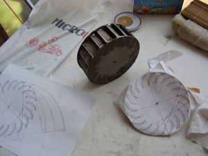
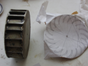
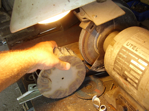
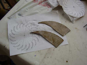
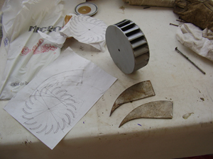
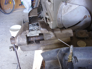
Successivamente ho disegnato il disco con le palette ed ho riportato i punti dalla carta al metallo. Nelle foto sono illustrati i vari passaggi fino alla verniciatura.
Subsequently I have designed the disc with the blades and have brought back the points from the paper to the metal.
In the photos they are illustrates you several the passages until the paint job.
Questo è tutto...!
Ciao Steeolico
This is all a... ! Ciao Steeolico
