Axial Flux Motor & Controller Making Update
Hi,
I've uploaded a new & improved manual for making a new & improved 3-phase solid state motor controller to "Manuals" at http://www.TurquoiseEnergy.com/ . I think this controller is kind of unique in that it forms one (in-field removable) side of a wiring box and all the wiring connections and all the bits of electrical equipment are totally enclosed in the box. You could use it for various motors from 12 to 36 volts (or more) by selecting suitable MOSFETs and a few component values.
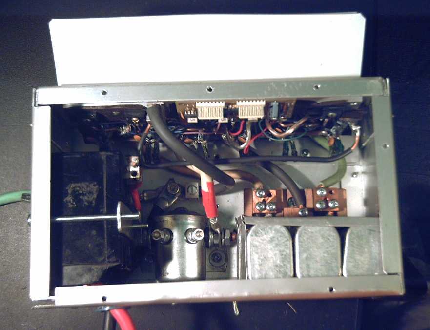
motor controller/wiring & equipment box
The motor's mechanical parts, as previously mentioned, can be made from car brake disk rotors and a car or trailer axle, hub and bearings. The 9 coils are wound and mounted individually and it uses a dozen supermagnets, akin to the wind plants except it's six doubled-up magnet poles.
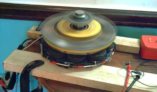
Motor spinning on bench with new controller
In response to complaints, most of the pictures are bigger and the formatting is better. (As I feared, trying to manually put the "real" pictures back in and tweak the automatically generated .html output of the W/P brought out the worst behaviour in the HTML editor and I spent 4-1/2 hours to do what should have been - well, it should have been automatic!)
Thanks to Oztules, I had to redesign the logic circuits in the motor controller around the MC33033 Brushless Motor Controller I.C. chip and scrap my own cherished design that used a few general purpose chips. The chip count only went from 5 to 4, but they're all smaller chips and the pin count went from 78 pins to 44. The 'passive' components pin count dropped similarly. No doubt it will do an optimum job of running the motors, and I did a proper little circuit board for it. (Luckily I hadn't got very far along doing one for my original circuit. Thanks ON semiconductors and Oztules!)
I finally got the new controller tested at the end of July. It works great! I made a way to clamp the motor onto a workbench. I ran it at 12, 24 and 36 volts, and ran it up to 1000 RPM. (Yay, I can measure the RPM now - any phototransistor output gives Hz on meter, Hz x 20 = RPM.) There are a few measurements of idle currents in the July newsletter. (#18) At 1000 RPM, bits the magnets had picked up over time were flying off at me and I was afraid to go faster. The whirring magnets were fanning a good breeze, which is very good and what I hoped for for keeping the motor coils cool. (It did hit about 1500 RPM later, again not the limit at all.)
I did some working out of copper losses for the motor, thanks to jimovonz pointing out the simple and obvious math for doing so. Some figures are in the May or June issue of the newsletter (#15, #16). The top steady-state currents I was seeing in more recent tests were around 75 amps (in one phase wire), so the maximum power (in and out) is a bit lower than I was writing of previously.
With all that and other things to do too, I haven't got much farther so far on the magnetic torque converter for variably coupling the motor to the wheel, or the new chemistry batteries to make "hybridizing" a car more practical.
Cheers,
Craig
PS: Now off for a few days camping.
