Author Topic: 12v powering 4 LED's - No resistor idea?  (Read 22517 times)

0 Members and 1 Guest are viewing this topic.

gotwind2

  • Sr. Member
  • ****
  • Posts: 383
  • ben[at]gotwind.org
    • Gotwind - The Renewable Energy Resource
12v powering 4 LED's - No resistor idea?
« on: April 15, 2007, 08:56:20 PM »


I've been playing with 10 mm White LED's again today from a 12 volt supply.


As the picture shows, I am running a string of 3 white LED's in series; (3 x 3.6v = 10.8 volts) plus a fourth standard red 5 mm LED with a forward voltage of 2.2 volts.


This gave me 13 volts with no resistor needed - I am assuming resistors are bad and waste energy as heat - The red LED only consumes 2Ma according to the spec sheet, is this less than a resistor? - I am unsure.


I tried it with a 12v battery (not much charge 11.8v) and it read a current draw of just 17 mA and it lit all 4 LED's adequately, I think a fully charged battery would work well and many strings of 4 LED's could be wired in  parallel. The red LED could be covered up with black tape if required.


Thoughts welcomed - 'ghurd' has been very helpful in the past, much appreciated.


Ben.

Spelling and typing is my strong point - not electronics :)

« Last Edit: April 15, 2007, 08:56:20 PM by (unknown) »

commanda

  • Hero Member
  • *****
  • Posts: 731
Re: 12v powering 4 LED's - No resistor idea?
« Reply #1 on: April 15, 2007, 03:58:33 PM »
Just a thought ................ and a bad one at that


Led's are current operated devices. The voltage drop across them is nothing more than a practical nuisance. The ideal led would behave the same as an ideal zener diode. Below a certain voltage, they would draw no current. Above a certain voltage, they will draw as much current as the supply can deliver.


In your case, it only works because the leds are not perfect zeners, and the battery voltage just happens to be at one particular sweet spot. What happens when that battery is being charged, and the voltage is approaching 15 volts. What is your led current then?


And if resistors are bad and waste heat (energy), what do you think that red led is doing, especially if you cover it with black tape.


The correct way to power an led is with a constant current source, so that the current remains constant irrespective of battery voltage. A series resistor can approximate a constant current source over a limited range of input voltage, if the difference between battery voltage and combined led voltage is high enough.


Some worked examples;

R = E/I

E = Vbatt - Vled

I = 20mA

Vled = 3.6 volts

Vbatt = 11 to 15 volts


for one led, the resistor value at Vbatt = 11 volts is

(11 - 3.6) / 20mA = 370 ohms

when Vbatt is 15 volts, this resistor will give an led current of

(15 - 3.6) / 370 = 30.8mA


for two leds, the resistor value at Vbatt = 11 volts is

(11 - 7.2) / 20mA = 190 ohms

when Vbatt is 15 volts, this resistor will give an led current of

(15 - 7.2) / 190 = 41.1mA


You can see the trend. I leave it to the interested reader to calculate values using 3 leds.


Amanda

« Last Edit: April 15, 2007, 03:58:33 PM by commanda »

Nando

  • Hero Member
  • *****
  • Posts: 1058
Re: 12v powering 4 LED's - No resistor idea?
« Reply #2 on: April 15, 2007, 04:03:21 PM »
BEN:


With LEDs resistors are the GREATEST invention to protect the LEDs for over current and burning up.


The LED voltage varies from maker to maker and, as well, also this due to temperature variables that the LEDs suffer.


LEDs are NOT voltage devices, LEDs ARE CURRENT devices, in principle.


Best, BEST is a PWM constant current source which reduces the Resistors LOSSES if well designed.


Do not try to CIRCUMVENT Physical and electric principles.


Nando

« Last Edit: April 15, 2007, 04:03:21 PM by Nando »

johnlm

  • Full Member
  • ***
  • Posts: 244
Re: 12v powering 4 LED's - No resistor idea?
« Reply #3 on: April 15, 2007, 05:45:03 PM »
And, if you are drawing 17 mA through the white LEDs and the red one is in series with the white ones, it has 17mA going through it also.
« Last Edit: April 15, 2007, 05:45:03 PM by johnlm »

ghurd

  • Super Hero Member Plus
  • *******
  • Posts: 8059
Re: 12v powering 4 LED's - No resistor idea?
« Reply #4 on: April 15, 2007, 11:41:37 PM »
Hi Ben,

Put the safety glasses on!  They're gonna Blow!


"Do Not use Internet LED math"  It is always wrong.  Always.  

Measure the ma.  You did that, and that is good.


The circuit in the photo is like a garden hose.

If it's going in one end, it is coming out the other.


Guessing the red LED is high Eff.  Meaning mostly it is like on the front of a VCR and lights up well with 1ma, but is not bright with 20ma.

Great for the VCR or DVD, but it won't light up a room.  The red frequency will help if the room has any stuff in the red spectrum, so don't cover it.


The 17ma is luck. (because the math is wrong)


A 12V battery is 'dead' at 11.9V.  This battery was at 11.8V.

A full battery at 12.67V, or a charging battery at 14.4V will have MUCH different readings.


If the battery was at 13.0V, I would expect the current to around double, maybe more, with the thoughts I have right now.  Shortening the life exponentially.

LEDs are fickle creatures regarding V:I.  You never can tell.

My last batch of LEDs run over 60ma at 3.6V.


I prefer the resistor as a current limiter. For a few reasons...

-It gives an indication of the battery voltage.

-The ma are reduced (longer battery life) as the battery voltage is reduced.

-No stuff to fail. (when is the last time you saw a resistor fail if nothing else caused it?)

-It won't go "Click!  I'm done. It's dark now." or flicker at the end.

-There is plenty of warning before the battery is dead and leaves the area dark. Sometimes months, because they are running at <2ma.

-The losses are very small in a well designed light, with good LEDs.


Disclaimer.  

I usually deal with 'micro' systems or alkaline batteries for LEDs.

A 5KW system draining 5000AH batteries at 0.2W could change my perspective.

G-

« Last Edit: April 15, 2007, 11:41:37 PM by ghurd »
www.ghurd.info<<<-----Information on my Controller

richhagen

  • Hero Member
  • *****
  • Posts: 1597
  • Country: us
Re: 12v powering 4 LED's - No resistor idea?
« Reply #5 on: April 16, 2007, 05:41:06 PM »
Hi Ben, I've had 4 LED's connected in series for 12 volt lighting before in the past.  I don't do that anymore for the reasons Commanda stated.  At the time I was thinking that since the LED's were not ideal, but were springy, I would get the highest percentage of my power out as light instead of heat.  This however leads to several problems:


First, Basically, when LED's fail, they often fail to a short circuit.  In your case, with 4 led's in series, if one fails, they will likely all fry in the string as has been my experience with similar setups.


Second, the light output varies dramatically with the battery voltage.  It the battery is full, the light will be bright, but when the battery is discharging, the light output will reduce dramatically.  


Third, not all LED's in even the same batch have identical Vf and Imax, or possibly these values change over the life of the device.  From my experience you get better results in the long run if you don't drive them near their limit.  The LED's efficiency appears to be a bit higher when not driven so hard.


So now I basically run three in series with a 180 ohm resistor and just add more LED's to make up the brightness for 12 volts.  For the future, I am thinking about using some of the larger LED's such as CREE's 70 lumen per Watt model.  For that type of LED I will likely use a constant current type circuit driver as that should keep the overall efficiency fairly high, and protect the string to some extent if one LED fails to short.  For now though, that is just hopeful thinking.  Rich

« Last Edit: April 16, 2007, 05:41:06 PM by richhagen »
A Joule saved is a Joule made!

mrpackethead

  • Newbie
  • *
  • Posts: 10
Re: 12v powering 4 LED's - No resistor idea?
« Reply #6 on: December 26, 2007, 12:29:43 PM »
i, ive just been trying out some new drivers from national semiconductor. These are certainly not the 'simplest' circuits that you could use, but they work very well, and they are not very expensive, or tricky to put together.. You can even use the online design tools ( my web-bench ) to design your circuit, based on the various paramters you want to use..


In particualar, i've been working on drive circuits to use with 1 and 3W luxeon clones. using a current limiting resistor just is'nt that smart, it generates way too much heat. The driver i've been using is an LM3404HV which is able to run on a input voltage of between 7 and 75VDC. Its a buck psu cirucit, so it requires an external inductor, cap and diode, plus a couple of resistors. Efficency is really good, i've got over 90% out of it in some configurations. Its going to cost you a couple of dollars to build. Its got a logic level dim control, which you can attach a logic level pwm signal to ( such as the pwm output of a pic ), and get dimming control out of.


The design is is such that the output current is almost constant across the entire input voltage. Its probably mostly appropriately for higher power circuits, ( say >300mW ), anythign less, you'd probably be best doing something simpler..


for more info, check out


http://www.national.com/appinfo/power/led.html


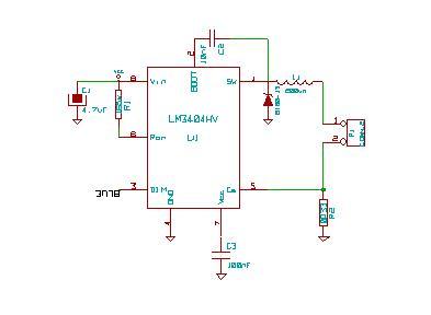
I'm using this driver for my christmas led lighting, and i'm pretty impressed by it.. The circuit below is for a single 3W Blue LED, runnign at 700mA, 3.55V, Rd 1ohm. note, i want to dim the led using PWM, so there is no Capacitor across the output. If you just want to run them consistantly, you can reduce the size of the inductor, and put a cap in parrallel..


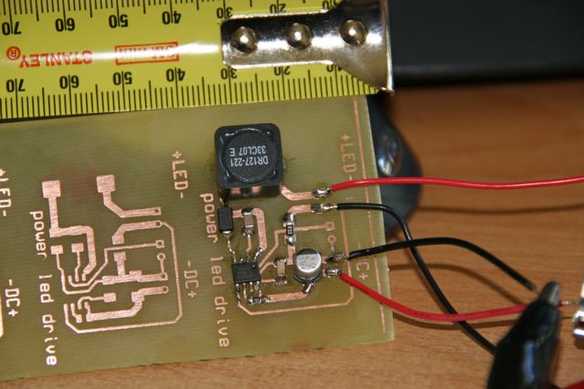
And now also a picture of the first prototype board for this circuit


« Last Edit: December 26, 2007, 12:29:43 PM by mrpackethead »

DamonHD

  • Administrator
  • Super Hero Member Plus
  • *****
  • Posts: 4125
  • Country: gb
    • Earth Notes
Re: 12v powering 4 LED's - No resistor idea?
« Reply #7 on: December 26, 2007, 12:43:14 PM »
Yes, neat!


I'm just not an inductance man: to me inductance and digital electronics means death from back EMF and even SCR-latchup!  Now, give me capacitive and resistive loads and I'm much more comfortable, but for this sort of arrangement where you're effectively getting a highly efficient switch-mode constant-current power supply, it's very good.


BTW, do you really solder those surface-mount things by hand?  I've always had shaky hands and find 0.1" pitch almost my limit.  I accidentally ordered some SMC parts the other day and immediately had to re-order DIL 0.1" packages instead.  Bv<


Rgds


Damon

« Last Edit: December 26, 2007, 12:43:14 PM by DamonHD »
Podcast: https://www.earth.org.uk/SECTION_podcast.html

@DamonHD@mastodon.social

mrpackethead

  • Newbie
  • *
  • Posts: 10
Re: 12v powering 4 LED's - No resistor idea?
« Reply #8 on: December 26, 2007, 07:25:15 PM »
Hi Damon,


Having the inductor there is'nt really a big deal. You've got to remember that this controller was designed to have one attached there.  And if you did'nt have one, it just would'nt work.. Nothign to be scared of there.


On that particular board, the components where hand soldered with a good soldering iron. Its not the neatest, but for this little prototype board was sufficent, given that theres no components on there that are really tiny.. I can hand solder TSSOP packages if need be, which are also smaller.  I also use a reflow oven that i built based on sparkfuns project, for some larger boards.. it does a great job..


 ( http://www.sparkfun.com/commerce/present.php?p=Reflow%20Toaster )..


I've actually got to the point now, that i pefer to use smd components over thru-hole for prototyping, because they are much easier to remove ( and clean up ) and change.. I've done at least 5 component swaps, without damaging the copper..     Good old solder wick, is one of your best freinds when doing smd stuff.. You can fix up most solder bridges with it no problem at all.  And theres quite a few components that are not available in thru-hole anyway now.


A.

« Last Edit: December 26, 2007, 07:25:15 PM by mrpackethead »