Author Topic: 3-phase vs. single-phase alternator  (Read 12234 times)

0 Members and 1 Guest are viewing this topic.

force9BOAT

  • Full Member
  • ***
  • Posts: 140
3-phase vs. single-phase alternator
« on: November 22, 2005, 07:51:06 PM »
Hello,


In reading the descriptions of alternator construction on OtherPower.com I've noticed that 3-phase seems to be preferred in larger devices.  I'm having trouble visualizing what the output curve looks like from a 3-phase alternator.  I'm guessing it produces lower peak voltage but at a higher AC frequency.  Is that correct?  I'm getting ready to build my second alternator.  The first one was a single-phase device.  I'm trying to decide how to wire my second alternator.  What would make you chose one method over the other?


Thank you,

Rob Miller

Kirkland, WA

« Last Edit: November 22, 2005, 07:51:06 PM by (unknown) »

cr8zy1van

  • Jr. Member
  • **
  • Posts: 60
Re: 3-phase vs. single-phase alternator
« Reply #1 on: November 22, 2005, 03:03:38 PM »
I think it all comes down to efficiency. I don't have the exact number commited to memory (yet) but I think that 3 phase gives you something like 63% more power in the same size system. You are able to pack more copper in, and reduce cogging and vibration, so its a win-win design.


I did a quick search for the subject, and came up with the following links:


http://www.fieldlines.com/story/2004/8/25/203324/088 and


http://www.fieldlines.com/story/2005/9/1/0550/49011
« Last Edit: November 22, 2005, 03:03:38 PM by cr8zy1van »

DanB

  • Global Moderator
  • SuperHero Member
  • *****
  • Posts: 2151
  • Country: us
    • otherpower.com
Re: 3-phase vs. single-phase alternator
« Reply #2 on: November 22, 2005, 04:43:23 PM »
Hi -


"In reading the descriptions of alternator construction on OtherPower.com I've noticed that 3-phase seems to be preferred in larger devices."


I'd say it's preferable in all size generators unless single phase AC is our final product.  If we're rectifying the output to DC, then 3  phase is the way to go.  Size is not an issue.


  "I'm having trouble visualizing what the output curve looks like from a 3-phase alternator.  I'm guessing it produces lower peak voltage but at a higher AC frequency. "


No...  the frequency and voltage can be whatever we wish in either case.  3 phase is delivered on 3 wires and at any time youll have single phase AC between any two wire.  Each set of two wires carries single phase AC.  So we sort of have 3 single phase outputs, except that they share conductors.  So we have current flowing through all the conductors all the time.  Single phase has at least a moment where no current is flowing in the line, during that time our whole machine, and the line between the machine and the batteries is doing nothing.  With 3 phase, everything is working all the time so were making more efficient use of conductors (and magnets).


When there's 0 current flowing in a single phase machine, there's also 0 torque required to turn the alternator.  At the peak of the sine wave (maximum current flowing) it takes maximum torque to turn the alternator.  So it 'cogs' while producing power.  You can feel that in your single phase machine if you short it out - itll feel stiff to turn, but very lumpy.  This makes noise and tends to rattle things apart.  3 phase is very smooth because we're making power all the time.


 "  I'm trying to decide how to wire my second alternator.  What would make you chose one method over the other?"


I would make it 3 phase!


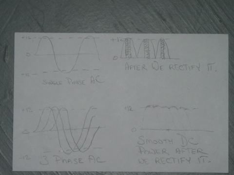
Sorry for the rough picture there..

But you can see in the picture at the top left what single phase AC looks like.  On the right top, is what you get if you rectify that to DC.  I put a line at the top there and called it 12V (imagine were charging a 12 V battery).  The DC is very lumpy, and current only flows when the voltage is over 12V.  With single phase, any time the voltage is below that line - our alternator and all the wires are doing nothing.  So at, or near cutin on a wind turbine - much of the time no current is flowing at all in a single phase machine.  Even at full output there would be a good deal of time where no current is flowing.


 The bottom left picture shows what 3 phase looks like and you can see that once we rectify it to DC we have very nice smooth (slightly lumpy) DC current.


Here is a good link that helps explain this too on Ed's page:

http://www.windstuffnow.com/main/3_phase_basics.htm

« Last Edit: November 22, 2005, 04:43:23 PM by DanB »
If I ever figure out what's in the box then maybe I can think outside of it.

willib

  • SuperHero Member
  • ******
  • Posts: 2414
  • Country: us
Re: 3-phase vs. single-phase alternator
« Reply #3 on: November 22, 2005, 05:33:53 PM »
If i may add something , for the same power output it takes  less copper in a three phase machine .

« Last Edit: November 22, 2005, 05:33:53 PM by willib »
Carpe Ventum (Seize the Wind)

force9BOAT

  • Full Member
  • ***
  • Posts: 140
Re: 3-phase vs. single-phase alternator
« Reply #4 on: November 22, 2005, 06:19:07 PM »
Thank you Dan,


I understand much better now.


Rob

« Last Edit: November 22, 2005, 06:19:07 PM by force9BOAT »

willib

  • SuperHero Member
  • ******
  • Posts: 2414
  • Country: us
Re: 3-phase vs. single-phase alternator
« Reply #5 on: November 22, 2005, 08:50:55 PM »
this is a another three phase graph


« Last Edit: November 22, 2005, 08:50:55 PM by willib »
Carpe Ventum (Seize the Wind)

nothing to lose

  • Hero Member
  • *****
  • Posts: 1538
Re: 3-phase vs. single-phase alternator
« Reply #6 on: November 23, 2005, 01:36:18 AM »
I have an odd question here.


Since single phase is lumpy and bumpy output, on/off sort of. Would that act in part similar to a pulse charger?


If 3 phase is always sending power, smooth currant, always on, then that would NOT act as a pulse charger right?


Now question, if I take a 3 phase machine, rectify each line seperate (3 brigdes) and run each to it's own battery bank, then would I in effect have a 3 phase machine, smooth output, always on, but get the pulsing effect to each battery bank from each seperate phase?


If that's somewhat correct and might work, then when I do my wiring here soon, I still need the batteries in the truck for portable power, I could easily wire a bridge so I can connect to the main house bank or the bank in the truck. The ones in the truck of course get abused alot, I like to pulse charge those every so often.


All bridges would be connected at all times, thus 3 phase, just to different banks instead of all to one. If you think it will work that way I'll try it, if not I'll probably just wire in a switch to flip from one bank to the other as needed like I first planned.

« Last Edit: November 23, 2005, 01:36:18 AM by nothing to lose »

dinges

  • Hero Member
  • *****
  • Posts: 1294
  • Country: nl
Re: 3-phase vs. single-phase alternator
« Reply #7 on: November 23, 2005, 08:13:12 AM »
Hi,


You're right about some batterytypes liking to be charged with pulsed voltage; I've built a batterycharger once, and when it was finished, I heard that batteries should be charged with pulsed voltage; rectified AC, unfiltered (no electrolytic caps) should do the trick, if you can limit current & overvoltage.


As far as a 3phase machine providing 3 separate single-phase voltages; this can be done if you have 6 wires coming from your alternator; i.e. 2 wires per phase, and none of the 3 phases internally connected; i.e. 3 completely separate phases.


Then you can individually rectify them and end up with three single phases; however, if you don't load all phases about the same, your alternator will see a lumpy load (vibration, etc.).


Perhaps you could also use 3-phase star, where you use 4 wires: 3 phase wires, and the '0' (zero) from the center of your phases. That's the way the utilities provide electricity: they produce 3 phase, but each house normally only gets 1 phase (& other wire being the common 'zero' of the star). Unless you have a 3phase electric connection, obviously. Since most houses use about the same power, the 3phase system is equally loaded (what goes for your little genny about 'bumpy-ness' also goes for the big one from your power company).


Like I said, I'm not sure whether in a 3phase star-situation (with extra 'zero' wire) you could individually rectify each phase; when each phase is completely separately available (6wires) you can.


Hope this is a bit clear; my explanation won't win a prize for clarity, I'm afraid.


Peter,

The Netherlands.

« Last Edit: November 23, 2005, 08:13:12 AM by dinges »
“Research is what I'm doing when I don't know what I'm doing.” (W. von Braun)

hpysheep

  • Newbie
  • *
  • Posts: 2
Re: 3-phase vs. single-phase alternator
« Reply #8 on: November 24, 2005, 09:32:17 AM »
Hi Rob,


Your question of 3 phase vs single phase power production is quite interesting when you refer to the prairie turbine site.  Prairie turbine is claiming to make 5500 watts of single phase power using a Nord 7.5hp 3 phase induction motor.  They claim to use one phase for voltage regulation, and one phase to generate electricity.....Up until I read that part, I was quite interested in Prairie Turbine's goal of creating a low cost, anyone can build, simple turbine.


If you look at their site, you see the reason they use a three phase rather than single phase motor is because it was readily available surplus from an industrial crane.


However, as they can only use one of the 3 phases to cogenerate power at a single phase household, they will only be able to extract about 2.5 hp which equates to about 1.7kw rather than the 5.5kw they claim in their breezy 5.5 ad.


If someone can correct me if my conclusions above are wrong, I would appreciate it.  Otherwise, Prairie Turbine should be looked at as another 'snake oil' sales site.


Gary

« Last Edit: November 24, 2005, 09:32:17 AM by hpysheep »

Goose

  • Jr. Member
  • **
  • Posts: 78
Re: 3-phase vs. single-phase alternator
« Reply #9 on: November 24, 2005, 07:33:00 PM »
((This makes me believe that the Breezy 5.5 should be renamed as the Breezy 1.7 as unless I am confused, 1.7kw is all you are going to get out of only one winding of a 7.5hp 3 phase motor.))


I haven't bought their plans yet, but from what I can tell you are using 2 phases.  If you stop and think about it,  220vac is using 2 phases(2 sets of windings).  Don't know what they mean by the 3rd phase is just voltage regulation.  I would guess it is something like making a phase converter, where you just energize the 3rd phase with caps.

« Last Edit: November 24, 2005, 07:33:00 PM by Goose »

tdmack

  • Newbie
  • *
  • Posts: 45
Re: 3-phase vs. single-phase alternator
« Reply #10 on: November 25, 2005, 12:58:51 PM »


Gary, first of all, thanks for your order.  You should be getting your plans today.


Not knowing how you arrived at your 1.7kw figure I'll explain how we arrived at ours.  The method we use is to actually clamp an amp meter to the supply lines to the motor and measure the current flowing in the circuit.  Then we use the formula: P= IV to arrive at the power being produced.

When Breezy 5.5 is max'd out (actually when our turbine begins to limit the torque applied to the motor shaft), we measure 23 amps flowing in the circuit.  Using the formula above we simply multiply 23amps X 240volts = 5520 watts (maybe we should call it "Breezy 5.52").


The power produced by the motor has much more to do with the turbine driving it then the size of the motor (easy guys, I'm still talking about asynchronous generation here).  If you connect a smaller motor to Breezy's turbine, a 5 hp for example, you would be over driving the motor and probably burn it up shortly (regardless of what the motor data plate says).  This is so much a fact with wind power that you can almost determine the power capabilities of a wind turbine by simply looking turbine it's self.  When comparing Breezy 5.5 to other types of turbines consider that Breezy's turbine is turning (and pretty much held) at speed around 120 RPM and is a four blade turbine over 18` in diameter.


Gary, I see that you have referred to our web site as "should be looked at as another snake oil site".  I must say that I find that remark quite offensive.  And as for myself I would be quite sure of my facts before making such a comment especially if I were as ignorant of the principles of this type of generator as you would lead us to believe you are by your statements.


In contrast we have done our research and also relied on the research of others to present this turbine and the plans for it.  But you don't have to believe me. In 1974 at the Technical Institute of Vaasa in Finland a study of how "squirrel cage" 3-phase motors excited and driven as generators behave unexpectedly under different wiring and load configurations.  I believe some of the results of that study may still be available at: http://www.saunalahti.fi/elepal/moottori/gener_e.html.  Also on a Danish website I have found an excellent description of the principles of asynchronous generation, you may want to take a look at this: http://www.windpower.org/en/tour/wtrb/async.htm .


Since I believe in the phrase "put up or shut up" I would like to extend an invitation to anyone wishing to see and measure the output of our turbine for themselves. We're located in central Kansas 20 miles south of Abilene.  My only request is that you call first so that we can schedule a time.  If you can't make it yourself and have a friend or relative nearby, we'd be happy to show them too.  You may find our contact information and a phone number at: http://www.prairieturbines.com

« Last Edit: November 25, 2005, 12:58:51 PM by tdmack »

force9BOAT

  • Full Member
  • ***
  • Posts: 140
Re: 3-phase vs. single-phase alternator
« Reply #11 on: November 27, 2005, 04:37:15 PM »
Dan,


One more question about this.  Your drawing on how to wire 3-phase shows the inputs as been A, B, C and the outputs are X, Y, Z.  That makes sinse to me but the 3-phase Basics doucment (http://www.windstuffnow.com/main/3_phase_basics.htm) says the outputs are A, C, E.  Looking at the drawings in both documents I don't understand why the 3-phase Basics document says the outputs are A, C, E.  Your drawing on the otherhand is very clear.  Which is correct?


Thank you,

Rob

« Last Edit: November 27, 2005, 04:37:15 PM by force9BOAT »

eliyahu

  • Newbie
  • *
  • Posts: 6
Re: 3-phase vs. single-phase alternator
« Reply #12 on: December 07, 2007, 12:06:58 AM »
I ran into a chap who re-wired a 3 phase induction motor into a generator that according to him worked fabulously. The motor he rewound was a 5 hp 1170 rpm 72 slot 220/440 volt.


As to what to do with the connection between b and c phase. From my understanding that is where you can put a resistance load and a capacitor. The phase sequence connection is important and needs to be determined so that a and b can be transformed and b anc c  be connected with resistance and a capacitor to help keep her in balance.


Does anyone have experience with re-wiring induction motors versus starting from scratch?

I have a 575 volt 3 phase 7.5 motor and was wondering if I could add poles to decrease the speed. She is 6 pole now and if I increased the poles to 18 then she would be producing at a much lower r.p.m. starting from 1165 (with slip)I suspect that I would start producing at about 450 rpm. Would this translate to too high a cut in?
I would rewire the stator. Then transform down to 240v then rectify and invert to grid  or rectify and choke for 24 or 48 volt for batteries.


For sake of specifics I have a 7.5 h.p.  6 pole 5.6 kw 60 hz 3 phase synchronous speed 1200 rpm. It has 48 slots in the stator. If I wired for 16 groups per phase using #18 wire how many turns would I need per phase group?


For the rotor how many magnets would I need? 3x6?


Any advice would be most appreciated. Great site. I remember seeing an article in a private power magasine that talked about required ratios. Anyone know of some good reference material?
Thanks


« Last Edit: December 07, 2007, 12:06:58 AM by eliyahu »

finnsawyer

  • Hero Member
  • *****
  • Posts: 1565
Re: 3-phase vs. single-phase alternator
« Reply #13 on: December 07, 2007, 09:28:52 AM »
Without comment I suggest you check my diary at this link.  The output of the design would be single phase.


     http://www.fieldlines.com/story/2006/4/21/16237/9933

« Last Edit: December 07, 2007, 09:28:52 AM by finnsawyer »

eliyahu

  • Newbie
  • *
  • Posts: 6
Re: 3-phase vs. single-phase alternator
« Reply #14 on: December 14, 2007, 12:37:59 AM »
I now see being new to this site that Zubbly would have been a great help.  
Can anyone refer me to some good reading material on this subject
Cheers
« Last Edit: December 14, 2007, 12:37:59 AM by eliyahu »

finnsawyer

  • Hero Member
  • *****
  • Posts: 1565
Re: 3-phase vs. single-phase alternator
« Reply #15 on: December 14, 2007, 09:17:08 AM »
Lumpy dc is no problem for lead-acid batteries.  If you are going to do this kind of comparison be honest.  Compare the waveforms and outputs for a three phase and single phase alternator having the same number of magnets and identical coils.  Say a 12 magnet 9 coil three phase versus a 12 magnet 12 coil single phase.  If the single phase puts out sufficiently more voltage it could give better performance.  That is, more output power.  While I haven't concerned myself with the standard single phase design, I have provided projections for my proposed design that show a considerable increase in output power using the same number of identical magnets and identical but 50% more, by number, coils.  As far as the times when the wires are not conducting current, that's irrelevant.  What's important is the average current flowing through the wires and the resulting heating or heat loss.  The only issue that I find of some consequence is the vibration issue and I'm not so sure about that either.  People may simply be interpreting sound from the coils due to the pulsed nature of the current as bad vibration, when it is not.  Of course, you always have the issue of the quality of the construction.  I really would not want to come to universal conclusions based of home brew experiences.
« Last Edit: December 14, 2007, 09:17:08 AM by finnsawyer »

finnsawyer

  • Hero Member
  • *****
  • Posts: 1565
Re: 3-phase vs. single-phase alternator
« Reply #16 on: December 15, 2007, 08:59:18 AM »
I got to thinking about this lumpy nature of single phase.  It seems that some people are working hard to take 3 phase dc and make it lumpy using mppt, which appears to be based on the Buck converter which uses inductors.  Why not take rectified single phase and do the same to it without using inductors.  The idea would be to design the alternator to match the wind turbine's output at the maximum wind speed.  For lower wind speeds you control the part of the half wave cycle for which conductance can occur using solid state circuitry.  This in turn would require knowing the RPMs of the alternator.  But that's related to the frequency of the rectified dc pulses.  It seems like that should be easier to do and cheaper than the mppt approach.
« Last Edit: December 15, 2007, 08:59:18 AM by finnsawyer »

joestue

  • Hero Member
  • *****
  • Posts: 1760
  • Country: 00
Re: 3-phase vs. single-phase alternator
« Reply #17 on: December 15, 2007, 05:12:45 PM »
In any case 3 phase/dc makes better use of copper in the transmission line, however, if the conversion of ac into dc occures at the alternator, then 3 phase may only make better use of the magnetic "space" or "area".


Since the coils are not overlapped nor magnetically linked, as they are in a car alternator, the difference between 1 and 3 phase's specific efficiency is minimal, if not more dependent upon the specific variations, not topology.


MPPT as far as i know needs some "intelligence", whether it be an analog circuit, or a 50 cent 8 bit micro controller.


If you are suggesting using silicon controlled rectifiers (SCRs) to control the output voltage, then the alternator will need to be rated significantly higher.

Reason is, I^2R losses are increased during voltage reduction.

At the cut in speed, the conduction angle will be the highest,

As the wind increases, the conduction angle must decrease, to avoid a stall.

What happens next depends on the alternator's resistance, and the blade's output power curve.

« Last Edit: December 15, 2007, 05:12:45 PM by joestue »
My wife says I'm not just a different colored rubik's cube, i am a rubik's knot in a cage.

finnsawyer

  • Hero Member
  • *****
  • Posts: 1565
Re: 3-phase vs. single-phase alternator
« Reply #18 on: December 16, 2007, 08:53:40 AM »
Three transmission wires are better than two?  I don't agree with that.  Place the wind turbine 500 feet from the diodes and batteries and see what happens.  Or use transformers to step up the voltage at the turbine and then down at the batteries.  Check the bottom line.  Every situation should be approached on its own merits.  Beware of all encompassing statements.


I don't know that I'd use SCRs.  I'd probably try an NPN junction power transistor with its emitter terminal in series with the positive terminal of the battery.  The base voltage would be held down until that part of the pulse cycle was reached for conduction to occur.  The transistor would either be cut-off where essentially no emitter current flows or hard on where the collector to emitter voltage is small, around 0.3 volts.  With 10 amps through the transistor when on the power dissipated in the transistor would be 3 watts or less.  Obviously, other circuitry is needed to track the turbine's power curve and determine the on time.  That's where the challenge is, but such circuitry need not consume much power either.

« Last Edit: December 16, 2007, 08:53:40 AM by finnsawyer »

eliyahu

  • Newbie
  • *
  • Posts: 6
Re: 3-phase vs. single-phase alternator
« Reply #19 on: December 16, 2007, 01:40:24 PM »
Hi Tim
My order for your book is in the mail.
I don't think that Gary was intending to slur you specifically (my read anyway) just to offer a warning.


In our conversation you referred to Dr. Gary Johnsons(K.S.U.s)Wind Energy Book. He makes the observation that the third leg of the 3 phase supply can act as a voltage regulator of sorts to provide balance. He advocates capacitors and a resistive load but as you pointed out on the phone unless you have a run away the resistance appears not to be necessary.


"An induction machine can be made to operate as an isolated ac generator by supplying the necessary exciting or magnetizing current from capacitors connected across the terminals of the machine"


I note that you are gearing up the motor to achieve your speeds. Have you calculated what losses are incurred? Adding a 4th blade to your prop clearly helps with this. (Marcellus Jacobs liked a 4 blade prop)


Can you offer a general explanation of what your controller does?


Grid tie at this level appears to be much more economical, avoiding the battery's and then inversion. So I see you guys as providing economical wind power. Well done.


« Last Edit: December 16, 2007, 01:40:24 PM by eliyahu »

joestue

  • Hero Member
  • *****
  • Posts: 1760
  • Country: 00
Re: 3-phase vs. single-phase alternator
« Reply #20 on: December 16, 2007, 04:21:58 PM »
I didn't say 3 lines were better than two, I meant to say 3 phase or dc is better than single phase, rectified or not.

Of course, if you rectify single phase and filter it, then transmission losses will be equal to any other dc source, and 2 wires w/i dc will have equal losses to 3 wires carrying 3 phase ac.


If you can find me anything other than a mosfet that will drop less than .8 volt, please, I'm all ears. (btw this voltage don't matter too much, since you got rid of the diode(s))


If I understand you correctly, then naturally commutated scr rectification is still more eff if it is three phase, at the turbine, on the tower.

all it takes is 3 diodes, 3 scrs, 3 capacitors, and 3 variable resistors.


what you want is on page 13 of this pdf:

http://www2.ing.puc.cl/power/paperspdf/dixon/21.pdf


and there is a bunch more here:

http://www2.ing.puc.cl/power/publications/electronics.htm


I hope that is of some help.

post a schematic please.

« Last Edit: December 16, 2007, 04:21:58 PM by joestue »
My wife says I'm not just a different colored rubik's cube, i am a rubik's knot in a cage.

finnsawyer

  • Hero Member
  • *****
  • Posts: 1565
Re: 3-phase vs. single-phase alternator
« Reply #21 on: December 17, 2007, 08:53:43 AM »
I don't know how long you have been frequenting this site and if you are aware of my proposed (single phase) alternator design.  You can find it here:


     http://www.fieldlines.com/story/2006/4/21/16237/9933


The arguments that I give show that for the same investment in magnets you can get considerably more power out.  That is where "the rubber hits the road" as I see it.


The junction transistors that I have known and loved all had a saturation (hard on) value of Vce in the 0.3 volt range.  This is true whether they were PNP or NPN.


To a certain extent an argument of SCRs versus Transistors is pointless.  You still need to control the on or conducting time and relate that to the power output characteristics of the wind turbine so as not to drive it into stall at any point along the power curve.  Both the single phase and 3 phase alternator output current have the basic frequency information built in due to the ripple.  You can pick that off by bleeding some current through a 100 - 500 microfarad blocking capacitor to a suitable resistor.  From there you can process the information any way you see fit.  You might need to add a resistor in series with the battery, although with a transistor in the off state in series with the battery you might not need to to get the basic information.


By the way, if the SCRs would work as you describe, why are people even bothering with the bulky and expensive buck converters?  

« Last Edit: December 17, 2007, 08:53:43 AM by finnsawyer »

joestue

  • Hero Member
  • *****
  • Posts: 1760
  • Country: 00
Re: 3-phase vs. single-phase alternator
« Reply #22 on: December 17, 2007, 08:42:35 PM »
I'm sorry, I had no idea that single phase could extract much more power out of a certain investment of magnets.


The reason SCRs are not used is due to increased copper losses as the conduction angle decreases.

If Scrs are used to reduce the voltage by 50% and 66%, but the average rectified current into the battery remains the same, then I^2R losses in the coil are going double, triple, respectivly.


Buck regulators maintain a full 120 degrees of conduction in a 3 phase rectifier.

In addition to this, if a buck regulator is used on a single phase unfiltered rectifier, than the conduction angle can be increased further, up to say about 150/160 degrees, at a dc output of 1/4 of the ac peak voltage. (on a sinewave machine)

PMA's oftem produce trapezoidal waveforms, and that won't be a significant difference.

« Last Edit: December 17, 2007, 08:42:35 PM by joestue »
My wife says I'm not just a different colored rubik's cube, i am a rubik's knot in a cage.

finnsawyer

  • Hero Member
  • *****
  • Posts: 1565
Re: 3-phase vs. single-phase alternator
« Reply #23 on: December 18, 2007, 08:43:25 AM »
There is no reason why one couldn't amplify that picked off ac ripple to a square wave.  That would give the full 360 degrees to play around with.  If I had sufficient motivation (someone paying me or urgent need) to work on such a design I would try the solid state - capacitance approach first before messing with inductors.  While I have a general idea how I would approach it, I do realize one may encounter unanticipated issues.  It might also turn out that the best design might require the use of linear amplifiers and both negative and positive power supplies.  One needs to determine the conduction or on time accurately.
« Last Edit: December 18, 2007, 08:43:25 AM by finnsawyer »