Author Topic: Wincharger  (Read 20246 times)

0 Members and 1 Guest are viewing this topic.

JoeD.

  • Newbie
  • *
  • Posts: 37
  • A Glenn Beck fan~ getting his talking points!
Wincharger
« on: August 18, 2010, 11:34:46 PM »
I bought this thing at a farm sale more than 20 years ago.
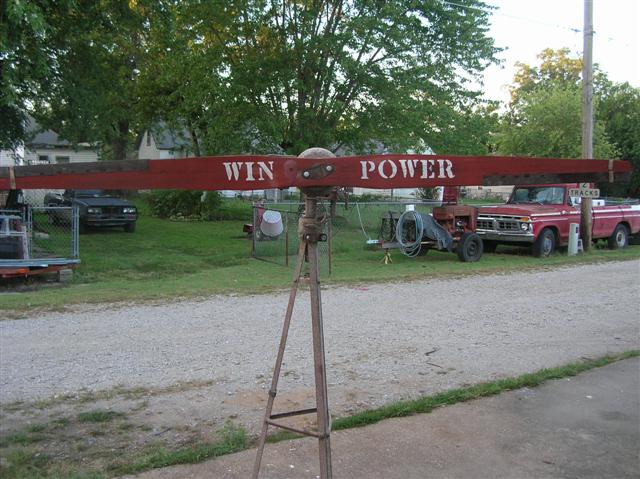


 I played with it for a while, tired of it, and sold it to a friend. It has been setting in his shed for all this time and all the metal is rusted. It still spins easy enough, but it need disassembled and lubed, then maybe painted.

Now that I am all gung-ho about this R.E. biz and want to experiment and have a good size amount of batteries to charge, I called the guy I sold it to and asked if he still had it and wanted to sell it back to me.

  It is a 6 volt unit. It has the original "charge controller"
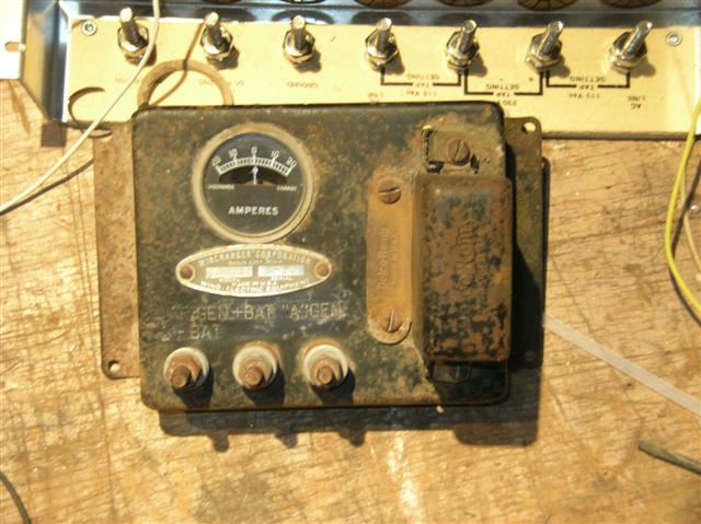
;).

 The prop is 72" and is made from some light wood- cedar or redwood I am thinking.
It has a couple of balancing weights on it. The teardrop shaped one on the front of the blade- I guess that is a balancing weight? The other is right atop the blade above the teardrop.  There is a thin copper sheet wrapped around the cutting edge of both ends of the blade, and another copper strip makes a band around the blade over those.
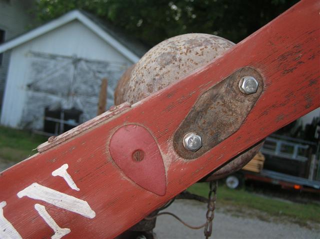


 Way back when, my dad painted it and restencilled the name back on it.

  When I first got it, it was missing the slip rings or whatever it used to get the power to the wiring system. I cobbled something up and it worked- back then.
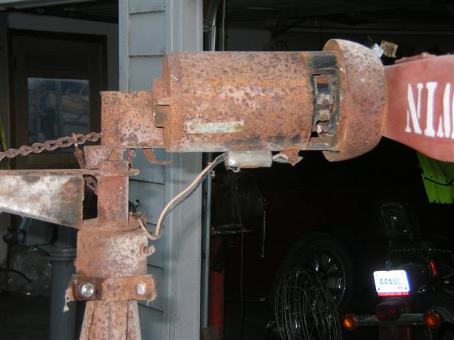


  At that time I had it mounted on a 25' tower outside my garage. I had no access to a 6 volt battery. I just ran the wires into the shop and connected them to the control. I had connected a 75 watt light bulb to the control terminals where the generator connected- not regulated. One night it was storming outside something fierce. Wind was howling. I looked out the back door of the house and could hear the blades whirring to beat hell, and a big gust would roar thru and the tail would furl and take the prop out of the windstream, and as the wind would subside, the spring would pull the tail back in line and the thing would roar back to life!

  I ran out to the garage and went back to where the control was (with the light bulb attached) and stood there and watched. While the wind was not so fierce, that bulb would glow dimly. But, when a gust would roar thru- that bulb would light up as if I had it plugged into a wall socket!-

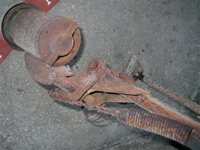
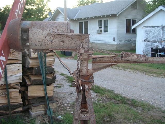


  Not real good pix, but I wanted to show you how it is all assembled.
« Last Edit: August 18, 2010, 11:40:18 PM by JoeD. »
Where I work, the motto is "We're not happy until You're not happy"

JoeD.

  • Newbie
  • *
  • Posts: 37
  • A Glenn Beck fan~ getting his talking points!
Wincharger
« Reply #1 on: August 18, 2010, 11:43:59 PM »
  The control has Delco Remy stamped on it twice- on the regulator housing and that little plate screwed to the face of it next to the regulator.  The makers plate has Wincharger Corporation, along with "Deluxe" as the model and there is also another number of which I forget. All in all that assembly is in good shape.

 I got to wondering~ would it be possible to make a different regulator to let the thing produce 12 volts instead of just 6? I wonder that because of how much juice it made during that windstorm in the previous story.

  Will it produce as much voltage as a regulator will allow it to (if it gets enough wind), or is it only good for 6 volts no matter what?

  If it is only good for 6, I may not have any use for it.......
« Last Edit: August 18, 2010, 11:46:47 PM by JoeD. »
Where I work, the motto is "We're not happy until You're not happy"

willib

  • SuperHero Member
  • ******
  • Posts: 2414
  • Country: us
Re: Wincharger
« Reply #2 on: August 19, 2010, 12:17:04 AM »
It looks like a DC generator, does it have brushes and a commutator ?

IIRC Dan B had one ,or was it someone that he knew that had it?

What makes you think it was only a six volt machine?  My guess is it is probably more..
Carpe Ventum (Seize the Wind)

hiker

  • Hero Member
  • *****
  • Posts: 1661
  • BIG DOG
Re: Wincharger
« Reply #3 on: August 19, 2010, 04:13:18 AM »
if you find out you have no use for it ..drop me a e mail.....
looks like a great restore project........
WILD in ALASKA

Flux

  • Super Hero Member Plus
  • *******
  • Posts: 6275
Re: Wincharger
« Reply #4 on: August 19, 2010, 04:53:38 AM »
It's not one that I recognise but few of these machines came here to the UK.

I have never seen a small wincharger with the furling tail and without the fan brake governor.

I strongly suspect it is 6v as most of these small machines were used to charge radio batteries. it may in fact be a standard 12v type car dynamo with 6v field to get a lower cut in speed. it could be a delco dynamo but I am intrigued by the fact that it is driven from the commutator end.

The control board will have a standard delco 6v cut out as fitted to cars of the day and an ammeter and a few fuses, there is no control as such, just isolation from the battery in low winds via the cut out.

Nice restoration project but don't expect much in the way of output.

Flux

JoeD.

  • Newbie
  • *
  • Posts: 37
  • A Glenn Beck fan~ getting his talking points!
6 volts
« Reply #5 on: August 19, 2010, 08:43:51 AM »
  Just went and looked at the regulator, and besides it being "deluxe" model,  the other info says "serial number" 30-6V, so I guess 6 volt.

  There is a small piece of metal tape with 6 digits riveted to the body of the generator- 161016 is stamped on that.

  I have the blade off, and could take some more pix. There are no fuses on the regulator/cutout

  I've been mulling over in my mind different ways to make a new, improved set of slip rings for it. Making a ring assembly would be easy- making something to house the brushes is where I come up blank.....

  Anybody have a opinion as to whether I could use it generate more than 6v. with a different type of control?
Where I work, the motto is "We're not happy until You're not happy"

XXLRay

  • Jr. Member
  • **
  • Posts: 78
Re: Wincharger
« Reply #6 on: August 19, 2010, 11:28:07 AM »
You could use a boost-converter (dc-dc-converter: http://www.powerstream.com/dc6-12.htm, http://www.current-logic.com/dcdc_converter_view.php?partnum=CA(H)) if you have (pulsed) direct current or an ac-dc converter or transformer if you have alternating current. They are available for multiple input an output currents. You could i.e. choose one with 5V input dc-current an 12V dc-output. Additionaly you have to check for its rated power.

tanner0441

  • Hero Member
  • *****
  • Posts: 1099
  • Country: wales
Re: Wincharger
« Reply #7 on: August 19, 2010, 02:40:39 PM »
Hi

As flux said it looks like a standard car dynamo from the 30s/40s I am sure one of the early Ford or MGs had the brushes at the drive end and most of the cars and tractors of that period were six volt.  The MG dynamo was mounted vertically down the front of the engine between the crank and camshaft and had a drive shaft that went right through, from memory the TC rings a bell.

I would be inclined to try a 12V car dynamo and see what happens.

Brian

Bruce S

  • Administrator
  • Super Hero Member Plus
  • *****
  • Posts: 5374
  • Country: us
  • USA
Re: Wincharger
« Reply #8 on: August 19, 2010, 03:30:56 PM »
JoeD;
What a beauty, where are you located, it is close to the street? I can get it in my Suburban :)?
Okay the generator as many have said is true generator.
If you have a few items to try, you can pull the wires coming from the generator and spin it up to see where the voltage peaks.
I'm guessing it will peak at about 8Vdc. Those types are wire wound for specific voltages.

I sent your specs to a restoration friend who deals in OLD cars. Ford, ramblers, AMC, Jeep ( before being bought my Chrysler), Studabakers, etc.

He's telling me it looks just like the Ford Deluxe types. VERY long lasting, he'll come back with more info when he has time, but is pretty sure of this. The 30 stands for 30Amps continuous output.

IF you decide to clean it up and use it, there are ways you can use the 6Vdc output with booster and wiring schemes to have it useful for 12Vdc as well.

You can also rewire it for 12Vdc :).

The regulator probably has "points' on it and are actually relays. They will be 6Vdc rated tooHave a close look at the regulator connectors, if there are tips or spikes on them get a finger nail file and smooth them out. The spikes will cause it to stick and arc.
Hot old motor oil will do the spring and chain a ton of goodness.

Cheers
Bruce S


A kind word often goes unsaid BUT never goes unheard

jlt

  • Sr. Member
  • ****
  • Posts: 368
Re: Wincharger
« Reply #9 on: August 20, 2010, 09:55:10 AM »
It is a 6volt gen .they will put out 12 volts at a very high rpm. But that puts too many amps to the field wires.and will burn out.I have replaced the field coils with ferrite mags . and mine worked pretty good.The control panel on them have a cut out on them . It is not a regulator.It is to keep the gen from running as a motor.. when there is no wind.Easy to get rid of just use a diode .The 6volt units are just a delco remy gen .The same one that came on  cars from built in the 19 forties. These are 2 pole generators so don't expect much out of them.Better to  just paint them up to look original and use for yard ornament.   

Old F

  • Sr. Member
  • ****
  • Posts: 309
Re: Wincharger
« Reply #10 on: August 20, 2010, 10:27:21 AM »
These 6 volt units were built to power a tube type  radio. 6v Dc was used for the tube filaments and a multivibrator  ( spelling? )  was used with a transformer for the high voltage section. 
Having so much fun it should be illegal

JoeD.

  • Newbie
  • *
  • Posts: 37
  • A Glenn Beck fan~ getting his talking points!
Wincharger
« Reply #11 on: August 20, 2010, 12:12:01 PM »
Well, there isn't any fancy way to rig up a deal to isolate the two batteries from each other, charge them simultaneously from the wind charger, but have them connected together and draw 12 volts from them?   That's not asking much..... ;D

  I'd like to do something useful with it, but don't have anything 6 volt.
Where I work, the motto is "We're not happy until You're not happy"

Tom Sullivan

  • Full Member
  • ***
  • Posts: 131
    • U.P. Solar Solutions
Re: Wincharger
« Reply #12 on: August 20, 2010, 01:28:09 PM »
I worked on a lot of truck electrical systems in my earlier years that used a "series parallel switch" (SP Switch).  The purpose of the switch was to allow a 12 volt DC system to charge and be utilized for all the systems on the truck except the starting circuit, where they used 24 VDC starters.  The SP Switch was simply a solenoid switch that connected the positive from two 6 volt batteries in a series (12 VDC) to the negitive side of two other 6 VDC batteries, in a series, and supplied 24 VDC to the starter.  There were a couple other terminals on the switch for dealing with the parallel charging of the batteries.  Haven't seen one of those for years, but the principal you're asking about has been done before.

Tom Sullivan

Flux

  • Super Hero Member Plus
  • *******
  • Posts: 6275
Re: Wincharger
« Reply #13 on: August 20, 2010, 03:30:45 PM »
Series parallel connection is ok if you don't want to use the power at the same time as you are charging. If that is not a problem then fine.

A boost converter could work but you need to know what you are doing.

The dynamo will not be suitable for 12 v directly, it will be too fast even if you can solve the field coil problem. Replacing the fields with permanent magnets will be better but it will still be fast but you will get something in good winds. It is not an easy conversion to do and it will be more of a labour of love than a useful process in view of the small amount of power it will produce.

A combination of change to permanent magnet and a boost converter properly applied would give the best results but it will need skill.

Series parallel connection may be the simplest option to make some use of it with no major modification.

Flux

kurt

  • Hero Member
  • *****
  • Posts: 925
  • Country: us
    • website
Re: Wincharger
« Reply #14 on: August 20, 2010, 05:45:23 PM »
if i had that thing flying i would hook it to a 6v battery then use a few small dc to dc a converters off ebay on the load side to run something useful like my router, modem, and answering machine for instance those run 24/7 use low voltage dc and draw very little power. perhaps if you got a proper dc to dc converter you could even run a laptop now and then but that would be a much more expensive dc to dc converter than just very small wall wort loads 

JoeD.

  • Newbie
  • *
  • Posts: 37
  • A Glenn Beck fan~ getting his talking points!
Wincharger
« Reply #15 on: August 20, 2010, 11:15:16 PM »
  The guy I sold it to who I bought it back from said what he wanted to do was use it to charge the battery he uses on his fence charger- it is 6 volt.

  I suppose I could take 12 volts worth of those Absolyte cells and do that series parallel thing and charge those. I would have to make some sort of manual operated switch gear to do that.

  If I am actually going to use it, I first need to design a simple brush/slip ring assembly to transfer the power from the gen down the tower to the point of use. I thought about incorporating the slip ring assembly off of an automotive alternator into it. The hard part is the brush holder assembly.

  The worst part of all this is that it will take some effort on my part!  :o  As I have gotten older, I am a lazy rascal. I have a nicely equipped machine shop and lots of friends with all kinds of neat project material I could use to make whatever I want, but I just can't hardly make myself get out of the house sometimes. Plus, it is so hot out that really cuts down on my motivation.

  Ideal situation is that I can buy whatever I need and not have to manufacture anything ;D.....
« Last Edit: August 20, 2010, 11:16:47 PM by JoeD. »
Where I work, the motto is "We're not happy until You're not happy"

willib

  • SuperHero Member
  • ******
  • Posts: 2414
  • Country: us
Re: Wincharger
« Reply #16 on: August 21, 2010, 12:18:14 AM »
I always liked mitcamp's sliprings

http://fieldlines.com/board/index.php/topic,137967.0.html

Here is another pic of them.


« Last Edit: August 21, 2010, 12:24:54 AM by willib »
Carpe Ventum (Seize the Wind)

Flux

  • Super Hero Member Plus
  • *******
  • Posts: 6275
Re: Wincharger
« Reply #17 on: August 21, 2010, 03:43:05 AM »
The original slip rings would have been very simple and probably crude. I expect there was one ring and the other connection most likely went via the yaw pivot.

You look to have a hole down the centre of the unit so why not drop a cable down there and forget the slip ring, most home built things run without any slip rings, unless properly built they are more trouble than they are worth.

Flux

JoeD.

  • Newbie
  • *
  • Posts: 37
  • A Glenn Beck fan~ getting his talking points!
Wincharger
« Reply #18 on: August 21, 2010, 07:50:20 AM »
Hey- thanks for the picture and the link. Good reading.

  My unit still has the original piece with the brushes, and I made the ring part when I had my unit the first time. It worked ok, but it was crude.  When I get home from work this evening I will take a pic of it and show what both pieces looked like.
« Last Edit: August 21, 2010, 08:03:38 AM by JoeD. »
Where I work, the motto is "We're not happy until You're not happy"

Shadow

  • Sr. Member
  • ****
  • Posts: 473
Re: Wincharger
« Reply #19 on: August 21, 2010, 02:32:46 PM »
Heres a link to Wincharger, lots of good info there.

http://www.wincharger.com/

jlt

  • Sr. Member
  • ****
  • Posts: 368
Re: Wincharger
« Reply #20 on: August 21, 2010, 03:18:50 PM »
My 6 volt wind charger has a hollow shaft that connects it to tower. forget about the slip rings and just run two wires down the shaft.Remove the field windings.and install mags in there place. and make a high tsr prop for it . mine made 13volts at 480 rpm.and would put out about 15 amps in 25mph winds.I have some pictures but  can't get them to post.My blades were only 5 ft.

jlt

  • Sr. Member
  • ****
  • Posts: 368
Re: Wincharger
« Reply #21 on: August 21, 2010, 03:23:09 PM »
I forgot to say It started charging 12v battery at 12 mph.

scoraigwind

  • Sr. Member
  • ****
  • Posts: 423
  • Country: gb
    • www.scoraigwind.co.uk
Re: Wincharger
« Reply #22 on: August 22, 2010, 11:39:34 AM »
What I find the most interesting about the photos is the furling system.  I have hardly ever seen one like this.  The furling axis is not the same as the yaw axis.  The turbine sits in line with the tail (which makes the tail's job a lot easier).  It's actually the turbine that furls, rather than the tail allowing the turbine to furl as in my own designs.  There is no side force on the tail, at least not at first.

It's easy to see where the Elliot Bayly Whisper 'angle governor' came from when you look at that.  Get rid of that spring - use gravity - you arrive at the angle governor.

Very interesting.

Hugh
Hugh Piggott scoraigwind.co.uk

JoeD.

  • Newbie
  • *
  • Posts: 37
  • A Glenn Beck fan~ getting his talking points!
disassembly question
« Reply #23 on: August 22, 2010, 07:22:06 PM »
 Took the gen apart a bit. Found one screw on the end that went thru the prop end housing. I thought that maybe it was holding in the bearing race.

  Well, turns out it is holding a brush clamp. I took the screw and clamp off, and when I reached back to try and remove the end cap I noticed the brush move...... RATS!. I didn't make any measurements on where it was located before it moved, and now I don't know what exact position it was in relative to the the brush it was next to.

  For reference, there are 3 brushes- 2 fixed and one adjustable. I looked on the Wincharger site and saw a mans' rebuild in progress and it had picture of a similar unit, but  not the exact thing. If I get this all the way apart, I'll snap a picture of it.

  What is required to get this particular brush back in sync with the other one?

  What am I adjusting the brush for?

  Are you adjusting the brush position to a position so that the gen starts ginning at a low speed or is it to adjust voltage output? I think if this was just an electric motor that adjusting the brush would either adjust the speed of the motor or the direction of rotation. I've had an old induction repulsiion motor that had adjustable brush spiders that changed just those things.


« Last Edit: August 22, 2010, 07:56:35 PM by JoeD. »
Where I work, the motto is "We're not happy until You're not happy"

don1

  • Newbie
  • *
  • Posts: 37
Re: Wincharger
« Reply #24 on: August 22, 2010, 10:20:54 PM »
Joe D

 The movable brush controls the output.  Don't worry about the position now.
 When that gen was used on a tractor you would set it according to what you did with the tractor.   Like use it all day in the field you  set it on low charge.  If the tractor is used say just to hall out the manure or short runs. you would then set it to high charge.
You know just off the top of my head I can't remember which way you move it for max output.   But if you need to know just e mail me at nash-@hotmail.com and I will look in the book and get it to you. I also have the tension springs and brushes for those old units if you can't find them locally.
 If it was important to use this at twelve volts you can get that armature rewound for 12vs and 12 volt fields are also available. The field housing is the same diameter as the 12 volt gens. You can rob the fields out of an old chev that is 12v and also plan on using the reg that went with 12v gen.  Note: you don't have to worry about low cut in. These turned really slow on the tractors and the cutout can be adjusted to kick in where you want.   If you ever want to try this just let me know and I will be happy to answer any questions if I can.
  have fun don.

JoeD.

  • Newbie
  • *
  • Posts: 37
  • A Glenn Beck fan~ getting his talking points!
brushes
« Reply #25 on: August 22, 2010, 11:09:44 PM »
Thanks for the info and offer, Don. The commutator wasn't worn appreciably and all I did to it was sand it down with sandpaper to brighten it up. The brushes still have lots of life left in them. I sanded off the armature poles to get the rust off of them, and same with field poles. Bearing were nice and quiet. They were both "New Departure C88503" bearings. Don't think I am gonna do anything to the exterior of the gen. for a while.

  I put it all back together. Put 6 volts to it- neg. to the field and pos. to the armature. It motors at slow speed. Didn't make any noticeable difference where the adjustable brush was setting.  If you lift up that adjustable brush, though, it speeds up to about twice the rpm it was doing.

  At the shop, I put the armature shaft in the lathe chuck and held the generator housing still with my hand.. Connected wires to the cutout in the proper places and connected a battery to that. Started lathe on w.f.o. (I think 1200 rpm) and could feel the generator load. Slowed it down to 637 rpm and looked at the amp gauge and it was charging 20 amps into that little 6 volt lantern battery. I slowed the lathe down to 307- the next notch- and if I remember right I don't think the cutout even cut in. Can't really remember for sure- I was just excited that it was generating at all. I was also in a hurry to get back home here to read and see if I had any replies as to where that brush needs set. I was thinking that maybe it would make a difference in when the thing started producing power.

  With the battery disconnected, it still made power. At the 637 speed, the no load voltage was over 12 volts.  I didn't do a whole lot of experimenting. I can, though, if anyone thinks up some things I should check on.

  I couldn't hold the gen housing and move that brush assembly at the same time to do any experimenting on output or startup speed..  It was a cobbled up mess, but the generator works!

  I used to have avariable speed wood lathe. That would have been perfect to turn the generator shaft at a particular rpm and be able to set the thing up to start making power at a certain rpm! Alas, I have no variable speed motor at this time.

  Just had a brainstorm- I have a bridgeport mill. I could clamp the armature shaft in a collet or drill chuck and hang it in the mill and clamp the gen body in the vise to steady it, and spin it there. It isn't a variable speed mill, but may have a better variety of speeds than the lathe does.

  I also have one other question about the basic operation of these things. Is there residual magnetism in the body of the generator that allows it to start generating electricity on its' own? The reason I ask is that this one still made power when I disconnected the battery during my testing. I wasn't sure if somehow the 6 volts was exciting the fields in this and making it work.  But, as I set here typing this I remember my story about the generator lighting a 110volt light bulb during a storm- and back then I didn't ever have a battery connected to the thing- so I think I have answered my own question!

   
« Last Edit: August 22, 2010, 11:24:59 PM by JoeD. »
Where I work, the motto is "We're not happy until You're not happy"

don1

  • Newbie
  • *
  • Posts: 37
Re: Wincharger
« Reply #26 on: August 22, 2010, 11:18:38 PM »
Thats great to hear. For something that has laid around so long and it still works. A testament to the design.

RP

  • Hero Member
  • *****
  • Posts: 722
  • A dog with novelty teeth. What could go wrong?
Re: Wincharger
« Reply #27 on: August 22, 2010, 11:45:11 PM »
Joe D

Have a look here for an explanation of 3-brush generators:

http://www.ytmag.com/articles/artint4.htm

Flux

  • Super Hero Member Plus
  • *******
  • Posts: 6275
Re: Wincharger
« Reply #28 on: August 23, 2010, 03:11:01 AM »
As others have said, don't worry too much about the third brush position, it mainly affects the maximum current and you probably won't even get there with that prop. it does slightly affect the cut in speed.

One field coil end will be connected to one main brush and the other coil end will go to the third brush. You will get highest output and lowest cut in speed when the third brush is nearest the main brush remote from the one the field id connected to. The lowest cut in and maximum output would be with the third brush removed and the field connected directly to the main brushes.

We used to remove the 3rd brush when trying to use car dynamos to get the lowest cut in speed.

Hugh raised an interesting point about the furling system and I can't see enough detail on the pictures to confirm some of my suspicions. If you could take a picture of the unit looking vertically down on it it would be interesting.

This is unlike any Wincharger i have ever met, in some ways it more resembles Paris-Dunn except for the furling arrangement.

Flux

joestue

  • Hero Member
  • *****
  • Posts: 1763
  • Country: 00
Re: Wincharger
« Reply #29 on: August 23, 2010, 04:38:16 AM »
sounds like some kind of anti-field regulation, if disconnecting it gets the highest output.
I'd say take that third field coil reverse the polarity and hook it back up to get even more output.
My wife says I'm not just a different colored rubik's cube, i am a rubik's knot in a cage.

JoeD.

  • Newbie
  • *
  • Posts: 37
  • A Glenn Beck fan~ getting his talking points!
Wincharger
« Reply #30 on: August 23, 2010, 09:08:18 AM »
Lifting the brush only changed speeds when I was motoring the generator. Didn't try that while generating.

  Here are some more pictures of the furling mechanism. Not very good definition between parts because everything is rust colored. In a few of them I held it in "furl" by hand to show how it operates.


Don't know if the spring is original equipment or not. Can't remember if I put that on it or not. Don't think I did. I may have put in what looks to be a stainless steel cotter pin- it hasn't rusted like everything else. Evidently the "moment of furl" is adjustable by wherever you hook the spring to the chain link.


  In this picture, you can see the brush holder for the slip rings at bottom left


  Can someone explain to me the forces that initiate the furling motion- on this or any other windgenerator?  On this one for instance, what forces are in motion that would make the blade turn its' face away from the wind? I really don't understand the principles involved here. I know it works, I just don't understand how.

  All I can see involved here is centrifugal force with the blade spinning, but can't see how it would make it do what it does.
« Last Edit: August 23, 2010, 09:39:52 AM by JoeD. »
Where I work, the motto is "We're not happy until You're not happy"

JoeD.

  • Newbie
  • *
  • Posts: 37
  • A Glenn Beck fan~ getting his talking points!
the next installment
« Reply #31 on: August 23, 2010, 05:24:29 PM »
   Took the generator back up to the shop and chucked it into the lathe.  Here is what I got with a D.V.M. with the battery connected to the generator output directly (as the load).

  1200 rpm   no load:29.3vdc     under load: forgot to write it down.

  637rpm      no load:12.5vdc     under load: 7.3vdc

  457 rpm     no load:6.8vdc       under load: 6.3vdc

  This is all unscientific, to say the least. I checked the amperage (charging that little rechargeable lantern battery) and at the 637 rpm speed it was putting out 3.05 amps running thru the gauge on the cutout.

  I moved the adjustable brush around while it was charging. It charged more as the brush was moved towards the fixed brush. I left it in that position and tightened it there.

  When the lathe was running in 457 speed the cut out stayed out no matter where I put that brush. The generator would be producing on the DVM, but the cutout never energized to send juice to the battery.

  Evidently it will take more than 457rpm to get this thing to produce. It will be interesting to see how much wind that takes.

  I'd also like to report that on someones webpage that they had pictures of the wind gen setup they were working on and instead of slip rings and brushes the guy used some sort of a universal joint made for electricity that used mercury to make the connection- it was semi- weatherproof he said.  I think it was on someones unit made from a Fisher-Pakel washing machine motor. I really couldn't make out how he had it mounted, but I think I'll do a search for that kind of revolving electrical connection.
« Last Edit: August 23, 2010, 05:28:43 PM by JoeD. »
Where I work, the motto is "We're not happy until You're not happy"

Flux

  • Super Hero Member Plus
  • *******
  • Posts: 6275
Re: Wincharger
« Reply #32 on: August 23, 2010, 05:31:38 PM »
Thanks for those pictures that does clear up the issues I couldn't see before.

The scheme is exactly as for the mark 2 Lucas freelite and as Hugh said it doesn't suffer from the offset during operation that the normal scheme suffers from, it does need another pivot capable of supporting the generator and this is a fairly well stressed point with bigger alternators ( generators).

I also agree withHugh that the SWWP angle governor is basically the same, whether derived from it or not. The Freelite used the tail weight as a control rather than the spring, the angle governor uses the alternator weight. If the second pivot is really well engineered then it is a better scheme than the conventional offset alternator and furling tail but it becomes a tricky bit of engineering for larger machines.

The offset operation of the common scheme doesn't significantly affect the performance but cosmetically it is bad especially if you have a right furling and left furling machine near each other, they look stupid when compared directly.

Flux