Author Topic: another solar tracker (DIY)  (Read 14922 times)

0 Members and 1 Guest are viewing this topic.

mab

  • Sr. Member
  • ****
  • Posts: 429
  • Country: wales
another solar tracker (DIY)
« on: April 27, 2011, 05:20:54 PM »
Hi folks,

Reading trackerJacks' post, I thought I'd post m own DIY tracker. I can't claim it to be original as the inspiration came from the redroc unit, but it works, it's simple, and it's been up and running since November 2009.

Besides, it's about time a contributed something to this forum as I've been sponging ideas off here for a couple of years.  ;).


This is the circuit diagram (hand drawn and poorly photographed, sorry). Basically two 5mm high-brightness red LED's positioned 45° east and west of the panel (and mounted so they turn with the panel) are wired in opposition.As long as they are seeing about the same amount of light the output from the opamp is about B+/2. If your using LED's as photosensors use reds - as you go through the spectrum from red to blue the signal you get out of them goes down.

the 1st op-amp is used as a high-gain low-pass amplifier. I used a 10Mohm feedback resistor but with hindsight I'd probably have used 1M or 3.3M. There's also a small capacitor (10nF) in parallel with the feedback resistor (but not marked on the circuit diagram). The op-amp is probably an LM301 or LF351 as I had a few of these lying about at the time.

The other four op-amps are used as comparators and are an LM324. the first comparator goes high if the signal exceeds the threshold set by trimmer pots. the output charges a capacitor via a resistor; I can't remember what value, but it was the highest value which didn't stop the capacitor from reaching the threshold of the next comparator. The resistor determines the time delay before the panel moves - to stop it chasing clouds across the sky. When the capacitor reaches B+/2 then the next comparator goes high operating the relay and driving the panel until the signal from the amp falls below the threshhold again. As the relays are 1600 ohm the LM324 can drive them directly.

Another thing missing from the diagram are the limit switches - these are microswitches wired normally closed and in series with the relay coils.

It worked OK in this configuration except that if the panel was all the way over to the west from day before,when the sun came up in the morning it could take a couple of hours to work out that the sun was behind it, so I modified it with 4 extra LEDs; two pointing 90° east and west,and two at 135°. it's been working for a year in this configuration and can find the sun as soon as it clears the trees / comes out. On bright overcast days it turns to face the open sky (i.e. about south). on very dull days it doesn't react.

There are some minor issues with it as it stands:-
The 10Mohm feedback it too high - even with the trimmers set to minimum sensitivity it reacts on days when the gains of moving less than marginal.
The delay provided by the RC network is only about 1min - too short - and occasionally it does chase bright clouds across the sky.  :(
I'm running it directly off battery voltage - 24V. the datasheet states that the max operating voltage for an LM324 is 28v so occasionally I exceed this; not had any problems yet though.  8)

Here's the actual solar panel and mount:
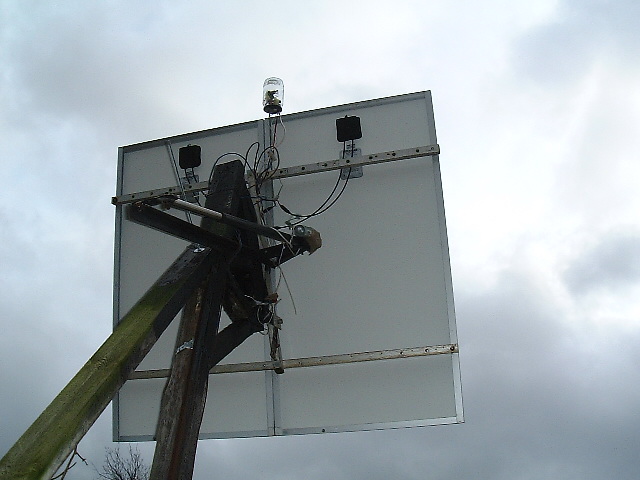


If your wondering (if you can tell from these pics) why it's cobbled together from a random mix of wood, angle iron and aluminium extrusion - it's because that's what I had lying around. The panels are Unisolar ES64's. The actuator I got off eBay - 24v 500mm 2000N (~450lbs?). It coped with the winter winds (2009 & 2010) OK (this site's got high hedges all around).


The electronics are in the pickled-onion jar.


This January I added a pair of 80W monocrystallines  ;D - and no, I'm not sure the mount can handle the wind loading; though it's managed so far, if any extreme winds are forecast I may tie a couple of ropes to it for the duration.

Hope it all makes sense - sorry my documentation is a bit lacking.

mab


oztules

  • Hero Member
  • *****
  • Posts: 1477
  • Country: aq
  • Village idiot
Re: another solar tracker (DIY)
« Reply #1 on: April 27, 2011, 06:04:30 PM »
Very nice first story mab.

When I see  electronics get built in a pickle jar, I just know we have a real DIY-er coming onto the board.

Good to see and welcome home.


................oztules
Flinders Island Australia

mab

  • Sr. Member
  • ****
  • Posts: 429
  • Country: wales
Re: another solar tracker (DIY)
« Reply #2 on: April 27, 2011, 06:14:28 PM »
Thankyou Oztules  :)

Having re-read my post a couple of other things bear pointing out:-

on the first comparators in the cuicuit, I think I've labelled the + & - inputs the wrong way round; with the output from the amplifier at B+/2, both comparators should be output-low; as drawn they'd both be output-high.

If your curious about the construction of the mount - the pivot axis is set at 52.5° from the horizontal - corresponding to my latitude here in eastern UK; i.e the east west pivot is parallel to the earths' axis of rotation.


The vertical adjustment is set every month or so (i.e. 24° up in midsummer; 24° down midwinter, and at the appropriate angle in between). And then the panel follows the sun accurately without having the complication of a vertical actuator & tracker.

I guess that's probably obvious to the veterans on this board but I though I'd I'd mention it in case it wasn't to the newbies  ;) .

TrackerJack

  • Jr. Member
  • **
  • Posts: 77
Re: another solar tracker (DIY)
« Reply #3 on: April 28, 2011, 01:21:16 AM »
The vertical adjustment is set every month or so (i.e. 24° up in midsummer; 24° down midwinter, and at the appropriate angle in between). And then the panel follows the sun accurately without having the complication of a vertical actuator & tracker

Besides, if you are like me, you like going out and adjusting every month or so just to have some hands on.

mab

  • Sr. Member
  • ****
  • Posts: 429
  • Country: wales
Re: another solar tracker (DIY)
« Reply #4 on: April 28, 2011, 09:22:52 AM »
Quote
Besides, if you are like me, you like going out and adjusting every month or so just to have some hands on.

Guilty as charged!  ;D

Although since the beginning of spring I've been more concerned about dumping the excess power from my new panels - we've had a very sunny spring and my dump loads are not really adequate - I've been plugging the passive fridge (actually an old chest freezer) into the inverter before going to work in the mornings just to make sure I don't fry the batteries.  :D

mab

TrackerJack

  • Jr. Member
  • **
  • Posts: 77
Re: another solar tracker (DIY)
« Reply #5 on: April 28, 2011, 10:28:55 AM »
Charge controller ??

ghurd

  • Super Hero Member Plus
  • *******
  • Posts: 8059
Re: another solar tracker (DIY)
« Reply #6 on: April 28, 2011, 10:53:33 AM »
ghurd controller,
to a ghurd timer,
to a relay in the 115V line,
to the fridge?

http://fieldlines.com/board/index.php/topic,145256.0.html

G-
www.ghurd.info<<<-----Information on my Controller

hydrosun

  • Sr. Member
  • ****
  • Posts: 399
Re: another solar tracker (DIY)
« Reply #7 on: April 28, 2011, 01:13:35 PM »
As I've posted here before, I've got my 8 cu ft chest freezer plugged into a 24 hour timer that turns on the power to the freezer from 10 am to 6 pm daily. That corresponds to when the batteries are more likely to be full. This works because I've super insulated the freezer so it doesn't have to run many hours a day to maintain the temperature close to zero F. It's using less than 400 watts/day.  I'm using a regular motor driven timer. If the inverter would normally go into sleep mode I would have used a modified electronic timer. Homepower magazine did an article several years ago about cutting the internal power line to the electronic timer circuit, causing it to run off the backup battery. When it activated the power relay the 120 volt AC would then take over powering the relay also. So the battery would only power the electronics and the initial turn on of the relay. The battery would last a long time. I used one for several years. For various reasons I now keep the inverter always on and can use regular timers.
You mentioned that you are using a chest freezer as a passive refrigerator. What temperature is it staying at. I assume you have extra water as mass but what prevents the food from freezing? Do you have a different thermostat installed?

mab

  • Sr. Member
  • ****
  • Posts: 429
  • Country: wales
Re: another solar tracker (DIY)
« Reply #8 on: April 28, 2011, 02:19:22 PM »
I think I should be more careful with my flippant comments.  :P

I've got charge controllers, the trouble is my dump loads are peltier heat pumps that are used to heat water (another story) and the solar panels now exceed their capacity.

I could just add some resistors (adding more peltiers will be fiddly - and I've run out of scavenged peltiers) but wanted to do something useful with it - hence using it to 'charge' the fridge (yes, it's got a lot of water as thermal mass). I've got a lot of work on at the moment so I've not got around to sorting things out properly.

Quote
ghurd controller,
to a ghurd timer,

I've got something like that in the pipline - actually thinking about using a microcontroller to turn the inverter (APC 1400VA MSW UPS) on and off rather than leave the inverter running 24/7, but not got around to doing it. I'm still learing about microcontrollers, but all it needs to do is monitor battery voltage and turn on (3 second press) or off (1 second press) and wait a set minimum time in between changes.  :)

Quote
what prevents the food from freezing?

nothing - if the food's in there it gets frozen - but I also have an old boat fridge (battery voltage) that I found dumped at the boatyard (it's amazing what people throw away); I can put the stuff in that if I don't want it frozen. when the sun goes away I can turn the boat fridge off and go back to the 'passive' fridge whilst the ice lasts. As long as there's ice in it it seems to stay <4°C - though I've not had experience of it's performance in hot weather.

I've only been using the passive fridge since November when the cold weather started - it worked passively 'til march and I've only been plugging it into the inverter since I had a surplus of power - thinking that I might as well 'charge it up' while the sun shines. Don't know how long the ice will last in warm weather, but there's only one way to find out.

mab

ghurd

  • Super Hero Member Plus
  • *******
  • Posts: 8059
Re: another solar tracker (DIY)
« Reply #9 on: April 28, 2011, 08:47:23 PM »
"I've got charge controllers, the trouble is my dump loads are peltier heat pumps that are used to heat water (another story) and the solar panels now exceed their capacity."

Capacity, schimacity.  Workarounds can be pretty easy... depending.

Tell us about you existing system.
G-
www.ghurd.info<<<-----Information on my Controller

TomW

  • Super Hero Member Plus
  • *******
  • Posts: 5130
  • Country: us
Re: another solar tracker (DIY)
« Reply #10 on: April 28, 2011, 09:08:20 PM »

Capacity, schimacity.  Workarounds can be pretty easy... depending.

G-

Easy for you to say being an eighth level grand master of the  black arts of electrickery.

Sorry, couldn't resist.

Tom


mab

  • Sr. Member
  • ****
  • Posts: 429
  • Country: wales
Re: another solar tracker (DIY)
« Reply #11 on: April 29, 2011, 07:58:32 AM »
Quote
Tell us about you existing system.

Urr... OK, I guess I should post it under user diaries. I'll try and do something today - It'll take a while 'cos I'm not a fast typist, and I need to remove the tv card to get pictures off my camera, and I need to turn the PC off to remove the TV card (Windows falls over if I unplug whilst running - don't ask me why).

I should warn you that my system wasn't really designed - it just seems to have evolved - with all the 'design flaws' that that entails.  ;)

mab

TomW

  • Super Hero Member Plus
  • *******
  • Posts: 5130
  • Country: us
Re: another solar tracker (DIY)
« Reply #12 on: April 29, 2011, 10:44:43 AM »

I should warn you that my system wasn't really designed - it just seems to have evolved - with all the 'design flaws' that that entails.  ;)

mab

I hear that. Mine has "grown in place" over a couple decades.

Undocumented, too.

Tom