Author Topic: Alternator Relationships of phases to multiples of 3 coil to 4 pole arrangements  (Read 21881 times)

0 Members and 1 Guest are viewing this topic.

Tall Paul Man

  • Newbie
  • *
  • Posts: 11
  • Country: us
Hi all,

Most of the axial alternators I have seen have been laid out in a 9 coil / 12 pole arrangement. I heard several times that more can be laid out if the 3 coil / 4 pole relationships is maintained. But my question is what happens if you drop the relationship to a 6 coil / 8 pole, or in my case 3 coil / 4 pole arrangement? Do you loose all the advantages of 3 phasing? In other words can a simple alternator be built using only 3 coils and 4 poles, and if so, what are the pros and cons?

Thanks,

Tall Pall Man

just-doug

  • Full Member
  • ***
  • Posts: 106
any coil count that evenly divides by three is a canident for three phase power.throwing in a addition pole is to avoid cogging.3 coil with 3poles would cog badly.

just-doug

  • Full Member
  • ***
  • Posts: 106
i thought a bit about your question .if i change "simple alternator"to "small alternator"..different discusion.i don't see why you could not use three coils with two poles and get it to charge batteries.wave form might not be great.

dinges

  • Hero Member
  • *****
  • Posts: 1294
  • Country: nl
But my question is what happens if you drop the relationship to a 6 coil / 8 pole, or in my case 3 coil / 4 pole arrangement? Do you loose all the advantages of 3 phasing? In other words can a simple alternator be built using only 3 coils and 4 poles, and if so, what are the pros and cons?

The 3:4 ratio is the simplest way to make a 3-phase alternator, but is definitely not the only way to achieve that. Different ratios are possible at the expense of more complication (overlapping coils, or needing to reverse the polarities of some of the coils). I wouldn't use or advise it for DIY axial flux alternators where you're relatively free on how to build it, but it may be a solution for certain motorconversions, where you might be limited by the number of slots.

This site has a very good explanation on all the different possibilities of coil/magnet-combinations that yield 3-phase alternators (technically, they're talking of motors, but it's the same for alternators). The site is in German though, but Google-translate may be able to translate it into something that is almost, but not quite, like English:

http://www.powerditto.de/Kombinationstabelle.html
“Research is what I'm doing when I don't know what I'm doing.” (W. von Braun)

Tall Paul Man

  • Newbie
  • *
  • Posts: 11
  • Country: us
I guess I should maybe make more clear my question is not just about 3/4 ratio but rather 3 coils and 4 poles, instead of 9 coils / 12 poles. If I make a small alternator with just 3 coils and 4 poles, do I get all the same effects as a alternator that uses 9 coils / 12 poles?


What is the main advantage of the 3/4 ratio? Does it make it run smooth? Better efficiency? Less copper??

Does it make more sense from a fabrication standpoint to have 4 strong magents and 3 big coils vs. 12 small magnets and 9 small coils?


If I wanted to be really simple is there any reason for me to not use just 2 magnets and one coil to make it simple?


frepdx

  • Full Member
  • ***
  • Posts: 100
I guess I should maybe make more clear my question is not just about 3/4 ratio but rather 3 coils and 4 poles, instead of 9 coils / 12 poles. If I make a small alternator with just 3 coils and 4 poles, do I get all the same effects as a alternator that uses 9 coils / 12 poles?
yes, basically the same.

Some reasons to use nine coils instead of three ... physical layout - you can get more area freed up in the center of the coil disk if you use more coils. Also, taking advantage of the best priced magnets and their size and aspect ratio drives the physical layout and the number you'll need to generate the power you want.

What is the main advantage of the 3/4 ratio? Does it make it run smooth? Better efficiency? Less copper??
runs smooth. theoretically you end up with perfectly even torque with a three phase alternator if it's laid out right -- perfectly sinusoidal output, equally spaced --> constant torque. It's also more efficient, copper wise, to transmit three phase.

It's more important in motors than alternators -- three phase motors have starting torque and direction without capacitors or shading coils.

Does it make more sense from a fabrication standpoint to have 4 strong magents and 3 big coils vs. 12 small magnets and 9 small coils?
It's a packaging exercise - with three coils you might be a little tight at the center where the shaft has to run. If the magnets are 1"x2" and you want to use three coils/four poles, turn them 90 degrees (orient them tangentially instead of radially). Same with the coils - that will give some more room for the shaft to run.

If I wanted to be really simple is there any reason for me to not use just 2 magnets and one coil to make it simple?
torque ripples, inefficient use of space.

« Last Edit: May 15, 2012, 03:08:22 AM by frepdx »

Tall Paul Man

  • Newbie
  • *
  • Posts: 11
  • Country: us
This is all making much more sense, thank you for your insight. But is a couple of more questions come up:

1. If I have 3 coils and 4 magnets do I have a 1 phase design? 6/8=2 phase, and 9/12= 3 phase?

2. Do 110v AC motors run more 'rough' than 3 phase motors? The reason I ask is all the 110v AC motors I have seen run seem pretty smooth to me.

frepdx

  • Full Member
  • ***
  • Posts: 100
This is all making much more sense, thank you for your insight. But is a couple of more questions come up:

1. If I have 3 coils and 4 magnets do I have a 1 phase design? 6/8=2 phase, and 9/12= 3 phase?
No those can all be three phase, assuming the coils are wired into three groups, everything's spaced evenly and laid out like the common axial flux design.  For three phase you need three coils (or three groups of coils) and a rotating field that excites them with a 120deg spacing.

2. Do 110v AC motors run more 'rough' than 3 phase motors? The reason I ask is all the 110v AC motors I have seen run seem pretty smooth to me.
110v AC motors are usually squirrel cage induction motors and not synchronous, they have 'slip' between the stator field and the rotor's 'squirrel cage' field. The PMAs we are talking about here are synchronous machines. So they don't make a good comparison.
« Last Edit: May 16, 2012, 12:46:30 AM by frepdx »

Flux

  • Super Hero Member Plus
  • *******
  • Posts: 6275
The basic single phase alternator has one coil per pole. You can make a version with one coil per pole pair where the flux converges to form a coincident or virtual pole. This is used in a lot of N American motors whereas British and European machines tend to use the full coil count.

A 3 phase winding has 3 separate machine windings spaced electrically at 120 deg electrical and is basically 3 single phase machines sharing a common pole count.

For your 4 pole machine, the basic single phase winding will have 4 coils so a 3 phase version will have 12 coils. You can bring this down to 6 coils with a coincident pole winding.

For normal radial machines with iron cores a 4 pole 3 phase machine would have either 6 or 12 coils and would have to be wound with overlapped coils. For a motor this is always done, but for battery charging with wind, the dominant factor is the winding resistance and the overlapped coils make it difficult to keep the Resistance low enough to be worth the extra trouble in winding and axial machines have the coils severely cramped at the inner and overlapping the coils is very difficult with the space available so a whole new breed of winding was developed by leaving out coils until the whole thing fitted on a single layer. The equivalent for your 4 pole case is 4 magnets, 3 coils. The 3 coil displacement still gives the 120 electrical ( and mechanical in this case) displacement and the result is 3 phase. A single phase machine would have coils directly under the magnets and have 12 or six coils ( the 6 coil version will probably confuse you as it has virtual poles so ignore it).

Single phase motors do run rougher than their 3 phase equivalent but with high speed and high inertia the difference may not be too obvious. In addition most single phase motors have a a capacitor kept in the starting circuit and effectively run as 2 phase machines and this is nearly as smooth as 3 phase. It is only the few machines that switch out the starting winding completely that run as single phase and these do tend to vibrate and hum more but the inertia hides it.

For wind power and battery charging the single phase current comes in short pulses and the vibration issues can be real and the low speed and inertia makes it worse.

By looking at how the 4 magnet 3 coil winding was derived I hope you can see that it is still true 3 phase but not all the available circumference is wound. What is wound though is done very effectively and for home build id very much easier to do. You will need a lot of skill and ingenuity to better it with a full coil winding.

Flux

GoVertical

  • Hero Member
  • *****
  • Posts: 691
  • Country: us
I did find a nice PDF file that shows many different configuration.

 http://www.rcgroups.com/forums/attachment.php?attachmentid=3707057
Learn from the past, live in the present, plan for the future
kilroyOdin is not here ;)
SEMPER FEROX

scoraigwind

  • Sr. Member
  • ****
  • Posts: 423
  • Country: gb
    • www.scoraigwind.co.uk
You can indeed use pretty much any combination of magnets and coils.  If the number is the same then you get single phase which I personally don't like because it vibrates.  I like the '3 coils to 4 magnets' design and have used it exclusively for about 15 years but I am not sure it is the best where you cram magnets close together.  I have been using neo magnets that are costly and been trying to get the best bang from that buck but lately have turned to look at using ferrite or ceramic magnets due to their better durability.  I have some old ferrite machines that I built in the 1990s that have no issues with magnets at all whereas neso seem to go wrong far too fast.  With ferrites I see the logic of piling them in tightly and then I think that smaller coils can have advantages.  See for example my latest project here. http://scoraigwind.co.uk/2012/05/photos-of-the-scoraig-wind-turbine-building-workshop/
Hugh Piggott scoraigwind.co.uk

tecker

  • SuperHero Member
  • ******
  • Posts: 2183
The thing you need to get right is the load . If you just want to make some voltage to play with in a small frame you can use  a small stator Your going to end up with some round coils and a situation that has weight and movement bt no real power . I have 6/ 8 stators that make some power in the order of 200 watts . To work with 12 volts and 3 coils you'll have 70 to 100 turns that will buck and you'll have the expenditure of hardware and a small output . The neos are expensive alright so save up and put up a couple of DC motor til then

 I always enjoy the folks that post from Scoraig a very dedicated group with Hugh at their side . The build with the Channel and the angle is perfect in a lot of ways  . I've talked about the weather invading the castings. A good possibility in the cold and wet with expansion .In the future maybe some enclosure . 
« Last Edit: May 20, 2012, 10:35:53 PM by tecker »

CraigM

  • Full Member
  • ***
  • Posts: 205
  • Country: us
You can indeed use pretty much any combination of magnets and coils.  If the number is the same then you get single phase which I personally don't like because it vibrates.  I like the '3 coils to 4 magnets' design and have used it exclusively for about 15 years but I am not sure it is the best where you cram magnets close together.  I have been using neo magnets that are costly and been trying to get the best bang from that buck but lately have turned to look at using ferrite or ceramic magnets due to their better durability.  I have some old ferrite machines that I built in the 1990s that have no issues with magnets at all whereas neso seem to go wrong far too fast.  With ferrites I see the logic of piling them in tightly and then I think that smaller coils can have advantages.  See for example my latest project here. http://scoraigwind.co.uk/2012/05/photos-of-the-scoraig-wind-turbine-building-workshop/

Hugh or anyone,

Is there a diminishing return when “cramming” ferrite magnets together on a rotor? Or would the ideal geometry for a ferrite turbine have wedge shaped magnets touching with little or no gap between them? And if this is the case the common rule of thumb of having a coil hole roughly the size of the magnet is thrown out the window. Should coils then be wound with a smaller inside diameter to pack as much copper as possible into a given stator size?

I recently purchase some large ferrite magnets and an inexpensive tile saw (wet, diamond blade) and found it's rather easy to cut ferrite magnets. This made me wonder if I should just cut them into wedge shapes and completely fill the rotors.

Thanks, CM
« Last Edit: May 22, 2012, 06:13:01 PM by CraigM »
Brain engaged in Absorption Charge Mode... please wait, this may take awhile.

Tall Paul Man

  • Newbie
  • *
  • Posts: 11
  • Country: us
So if I wanted to build a simple three phase design doing it with the least coils and magnets as possible, which from the list would be the best combination for running smooth? And is there another combination I am missing?

Coils / Magnets
1/1
1/2
1/3

2/1
2/2
2/3
2/4

3/1
3/2
3/3
3/4

4/1
4/2
4/3
4/4
4/5

frepdx

  • Full Member
  • ***
  • Posts: 100
So if I wanted to build a simple three phase design doing it with the least coils and magnets as possible, which from the list would be the best combination for running smooth?
For an axial design use three coils that bump up to each other and four poles.  For radial here's some simple ones. To get true three phase from 3 coils and two poles, the coils have to overlap, i think.

CraigM

  • Full Member
  • ***
  • Posts: 205
  • Country: us
So if I wanted to build a simple three phase design doing it with the least coils and magnets as possible, which from the list would be the best combination for running smooth? And is there another combination I am missing?

Tall Paul,

For a three phase design you need a minimum of three coils or one coil for each phase. You can do this with one magnet that travels 120 degrees to each coil but this is a very inefficient design.
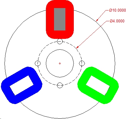

This image shows a simple three phase design with phases shown as red, green and blue. A single magnet is centered over the red phase. There's a lot of wasted space here and the magnet needs to rotate 120 degrees from coil to coil. Not a good design.
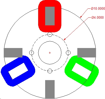

This image shows the same three coil layout but now with four magnets. The rotational amount the magnets travel from coil to coil is reduced and this in turn increases the output of the alternator.

There is still a lot of empty space between the coils and between the magnets. If you fill this space with additional coils and magnets you further increase the output.
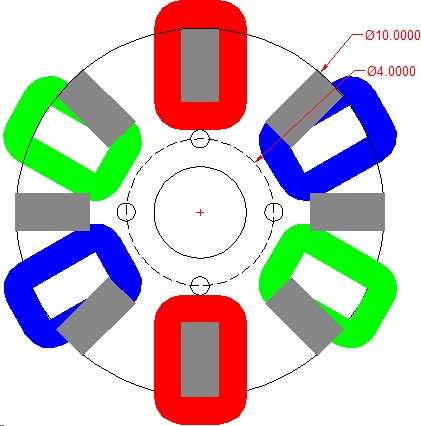

This image shows the same layout as above but with the addition of 3 more coils and 4 more magnets. This layout is now using all of the empty space available and is approaching the limit of coils and magnets that will fit the given rotor diameter. There are now two coils working in each of the three phases.

There are many ways to approach the coil/magnet geometry from single phase (equal number of coils to magnets) to polyphase of 2,3,4 or more phases. What you need to accomplish is that each phase sees the same geometry at any given point of rotation. If you look at the six coil design you'll see the 12 o'clock and 6 o'clock coil have the magnet centered.

Use a compass and protractor or a CAD program to draw out different design geometry and this will help you understand the variables. Also note the north - south - north orientation of the magnets. If your phase sees all the same pole (either north or south) then the coils will need to be wound all in the same direction. If you design has a phase seeing both north and south poles then your coils winding will need to be reversed. Example is cw for a north pole and ccw for a south pole.

Hope this helps.

Rgds,
Craig


Brain engaged in Absorption Charge Mode... please wait, this may take awhile.

scoraigwind

  • Sr. Member
  • ****
  • Posts: 423
  • Country: gb
    • www.scoraigwind.co.uk
You can indeed use pretty much any combination of magnets and coils.  If the number is the same then you get single phase which I personally don't like because it vibrates.  I like the '3 coils to 4 magnets' design and have used it exclusively for about 15 years but I am not sure it is the best where you cram magnets close together.  I have been using neo magnets that are costly and been trying to get the best bang from that buck but lately have turned to look at using ferrite or ceramic magnets due to their better durability.  I have some old ferrite machines that I built in the 1990s that have no issues with magnets at all whereas neo seem to go wrong far too fast.  With ferrites I see the logic of piling them in tightly and then I think that smaller coils can have advantages.  See for example my latest project here. http://scoraigwind.co.uk/2012/05/photos-of-the-scoraig-wind-turbine-building-workshop/

Hugh or anyone,

Is there a diminishing return when “cramming” ferrite magnets together on a rotor? Or would the ideal geometry for a ferrite turbine have wedge shaped magnets touching with little or no gap between them? And if this is the case the common rule of thumb of having a coil hole roughly the size of the magnet is thrown out the window. Should coils then be wound with a smaller inside diameter to pack as much copper as possible into a given stator size?

I have been playing with the above idea in my most recent alternator.  You can now see more details here http://scoraigwind.co.uk/2012/05/clearer-drawing-of-the-10-pole-12-coil-design/  If there is no gap between the magnet poles then I agree that you can do well to make the coils smaller. 

However I do find that adding more coils increases the number of holes in the middle of coils and so the holes have to be pretty small or you lose out on wires.  Just how small to make those holes and still get a return from the inner turns is an interesting question. 

You can make the poles smaller and get smaller coils but small poles jammed together suffer a lot of leakage and this can be a problem with large air gaps.  One thing is for sure - I don't recommend gluing magnets of the same polarity side-by-side to make large polkes unless you really have to.  It's possible to do with ferrites but not simple, and if you don't glue them evenly you can lose out on air gap clearance that way too.

Hugh
Hugh Piggott scoraigwind.co.uk

Flux

  • Super Hero Member Plus
  • *******
  • Posts: 6275
I think we need to decide on the application before taking things to seriously. If we rectify to charge batteries then things are rather different.

In the above drawings that Craig has produced things will be ok if rectified but the first arrangement could hardly be regarded as a normal 3 phase generator when considering it as an ac machine.

In conventional use we deal with sine waves or an approximation. The 3 phase machine is basically 3 single sine wave machines in one housing and with the phases displaced 120 deg.  The strange thing shown in the first diagram is more like 3 pulse generators spaced 120 deg and the waveform would be so far removed from anything recognisable that you could hardly apply any of the 3 phase theory to it. When rectified as a battery charger it would have some similarities.

The second diagram now has coils coils partly under the influence of magnets at all times and with correct proportions can approximate to a sensible waveform and is about the simplest true 3 phase arrangement.

Regarding the question about cramming in magnets, that is difficult to answer. As a conventional generator loaded in the normal way it is not likely to be efficient in the use of magnet or copper, but for a direct charging wind machine then it can be effective to use more than the logical ammount of magnet to get a lower resistance winding.

As Hugh said it is far from easy to decide how far you can take this. Using rectangular blocks it seems reasonable to jam them in to the point where they touch at the centre. If they are arc shaped I can't believe it would be an advantage to cram them in to the point where there was no gap between them as the leakage flux would be so severe that you would almost certyainly get the same result with less magnet material.

Chance for someone to do a lot of experiment or devise a computer programme, beyond a certain point logic fails and occasionally someone tries something that seems silly but it works.

Flux

Tall Paul Man

  • Newbie
  • *
  • Posts: 11
  • Country: us
So this is all very helpful. Going to Criags post he shows:

Coils/Magnets
3/1
3/4
6/8

combinations. Even if the 3/1 and 3/4 might not be 'True 3 phase' would they still run smooth? And what about the 3/1 combination? Would that be prone to 'Cogging'? Thanks Craig for the great diagrams!

Tall Paul Man

DanB

  • Global Moderator
  • SuperHero Member
  • *****
  • Posts: 2151
  • Country: us
    • otherpower.com
they are all true.
The most common in these axial flux machines is any ratio of 3:4, and in my experience ~ it's pretty hard to miss a near perfect (if not perfect) sine wave.
If I ever figure out what's in the box then maybe I can think outside of it.

Flux

  • Super Hero Member Plus
  • *******
  • Posts: 6275
None of these ironless stators cog, the basic definition of cogging comes about as a result of change in reluctance and this only happens with iron cores.

Smoothness of running or vibration is a slightly different issue and all single phase machines show this effect. A true polyphase machine will have only a very small torque ripple and there is little difference between 2 , 3 , 5, 6 phase and with higher phase numbers it gets even more smooth.

I have every reason to suspect that stupid one magnet 3 coil combination would exhibit a torque pulsation as bad as single phase and I can't see any reason to consider it in that simple form as drawn with a single small magnet.

When you analyse it and re draw it with correct proportions then it then magically becomes a 2 pole 3 coil 3 phase winding and it would be ok but for every case the geometry is important. Not only do the pole and coil numbers have to be correct but the pole arc and coil span need to be correct for it to work properly. Just quoting magnet and coil numbers at random is not going to make a good machine.

Flux

CraigM

  • Full Member
  • ***
  • Posts: 205
  • Country: us
Tall Paul,

What is it that you're trying to achieve by using a very minimum of poles and coils? If you can elaborate on your intended goals this may help give the rest of us a better understanding of what you wish to accomplish.

The examples I gave are most commonly used in an air gap axial flux machine.

And no, don't even think about the stupid (LOL with Flux) single magnet design. It was used for demonstration only.

http://www.scoraigwind.com/CABLE/stator.html
Take a look at this animation and study it carefully. Note the location of the magnets at any given point and what it's voltage amplitude is at any given time in the cycle. The line graph on the bottom gives you the voltage in real time for each phase. Note where a magnet is at time of maximum voltage/amplitude, and everywhere in between. Note whats happening when a magnet is over the hole, over the coil leg, in between coils etc.

Regards,
CM

Brain engaged in Absorption Charge Mode... please wait, this may take awhile.

jlt

  • Sr. Member
  • ****
  • Posts: 368
     My first turbine was a 10 coil 12 pole machine and used 5 rectifiers and a neutral ring of wire hooking all the start windings  together.

     I have seen over 50 amps  a few times. and it is still working great. although the coils have turned pretty dark.

      The present design that Hugh   is using is using 9 coils and 9 rectifiers . Is it a better design?
   

jlt

  • Sr. Member
  • ****
  • Posts: 368
Also there was a design by jerry that used 12mags and 11 coils.

  and i think he used ceramic mags .