In my previous diary on the pipe furling system, I didn't show the generator mounting. This caused some confusion which I wanted to fix here. The photos below might help. They show two different attachment methods, but It is certainly possible to postulate others, especially for use with axial brake disk style alternators.
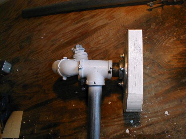
Above is a view of my original generator attachment scheme viewed from the front, windward side. Note the 1/4" bolts securing the pipes on the left side.
Here the generator is attached off to the right side of the mast facing the viewer. Possible adjustments are the length of the nipple between the "T" joint and the floor flange, the angle of the generator relative to the tower (Blades parallel to the tower or tilted up a bit), and the thickness of the support block, in this case a 2x6. Due to the fact that my generator is 8" in diameter, this scheme means the generator shaft is a full 8" + from the center of the mast, which gives the wind on the rotor more leverage for furling than I want. It also puts the full weight of the generator (almost 100 lbs including the hub and rotor weight) too far from the mast for my taste.
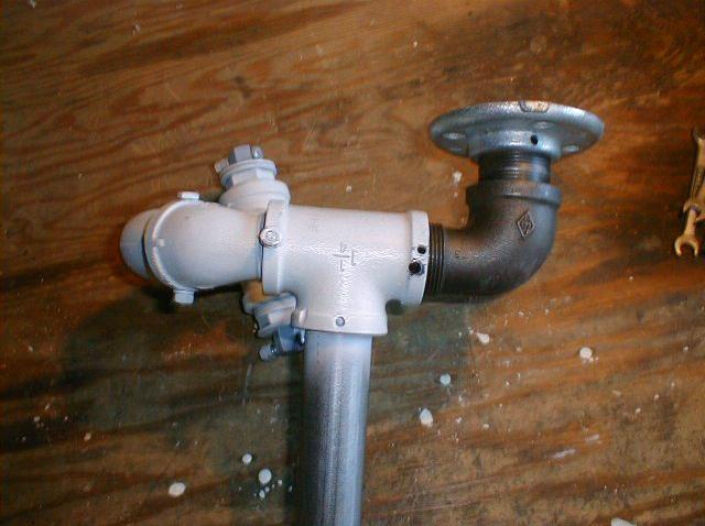
Above is the other version. In this the elbow positions the support platform above the "T" joint and off to the right roughly 4 inches from the mast center. This is closer to where I want the center of the rotor. If at some later point I want to experiment with different positions, I can easily drill out a new 2x6 and move the generator in or out from the mast (left or right in the picture).
This placement of the generator mount leads to several possibilities in useage and support options. It could be rotated forward to support an axial alternator design instead of the motor mount style. It is an easy modification to use 1/8" thick steel strapping as additional support from the support platform to the locking bolts on the "T" joint. This would further reduce the possibility of the pipes shifting position. Since the generator mount platform (the 2x6) is an inch or so above the "T" joint, a shim could be placed between the two pieces to relive the strain on the elbow joint.
For the truly paranoid, the joints can be super-glued and the pipes could be filled with epoxy or fibreglass resin after the locking bolts are installed.
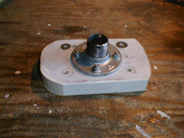
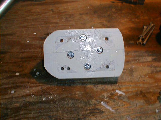
This shows a simple motor mount. A floor flange bolted to a 2x6 bolted to a motor mount. The motor/generator, omitted from these photos so the support details can be seen clearly, bolts to the opposite side of the 2x6 as the flange. The flange bolts are recessed so as to allow the motor to mount flush to the 2x6. The outline of the motor mount can be seen on the following photo.
This mounting aparatus is not sleek and sexy, but it is adjustable and with proper locking precautions should give a wind generator the support it needs to stay up and running with the wind for many years. Of course, who wants that when you can take it down and readjust it so easily ?
Chuck
