Here's a chickenscratch schematic of a little do-dad I put together using a couple of those heavy-duty relays from Radio Shack. These are the DPDT 15A @ 120v kind. Just make sure your two relays have matching windings. Using two of the same relay makes the most sense. Right?
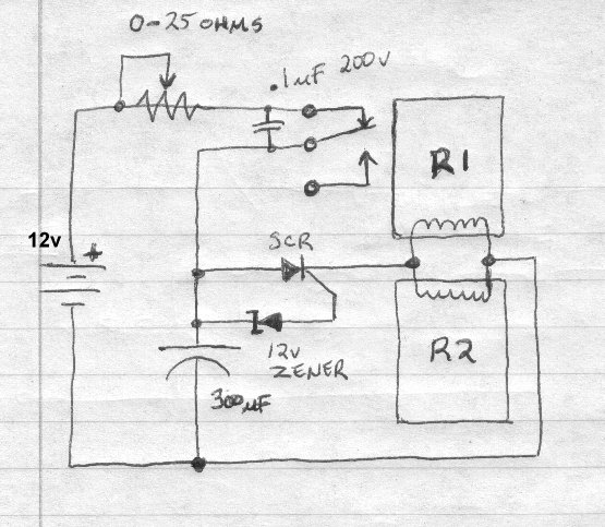
It's actually a pretty simple RC circuit. The two relay coils are wired in parallel so that both relays are activated at the sime time. The potentiometer is optional, but would give you a measure of control over how fast the capacitor builds up a charge before the SCR fires.
The contacts in R1 are only used for the internal power cut-off in the pulse control circuit itself. So, you could just build this pulse control around the single relay.
I put a .1uf cap across those contacts to reduce arcing as they make contact. A 20v DIAC or a couple of 20v zeners, back-to-back across there probably wouldn't hurt either.
Then build your flip-flop transistor control around the second relay (R2).
Then just tie the two windings together in parallel so that both relays pulse at the same time.
You can increase the size of the capacitor to increase the time the relays will be held on.
300uf is just about the minimum required to get both relays to turn on when they're paralleled like this.
My power source for the test model is actually about 14v peak voltage, so the 12v zener works just fine. It might be a little bit tempermental if your supply voltage was much lower than that. I just casually plopped that 12v source voltage in the diagram without even thinking about it. Sorry.
