Hello everyone!
I promised a little while back that i would make a posting with more explanation on how to make the magnet cage, use round magnets, use existing winding and what the best windings are to use. also an explanation on how to design a complete winding if you wish to do so.
This post is rather long with many photos and diagrams, but i am sure you will have a good understanding of the process after viewing the all of the posts.
I have just completed another conversion from a 2 hp 4 pole 3 phase for my brother. So i shall use some of the photos from it.
The first part we will deal with is what motor to select for using existing windings, and how to modify them or not.
In Canada the most common industrial low voltage motors we use are 575 volt 3 phase, however 230/460 volt motors are quite common and the most common in the USA to my knowledge. These motors have from the factory 9 leads which allow you to use either a single circuit 460 volt connection or a double circuiut parallel 230 volt connection.
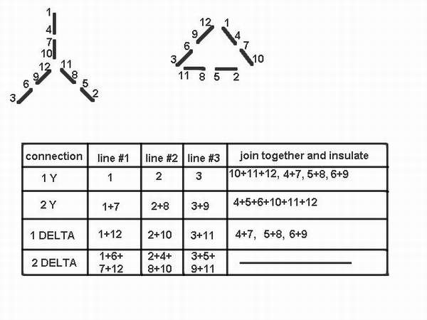
The most common winding that manufacturers use for this 1&2 circuit winding is of the Y connection. However, with a little operation to the winding and adding 3 more leads, you can have a 1&2 circuit alternator with both Y and Delta capability. This really gives you a lot more possibilities for cut in voltage and current carrying capability. You have to remove the lacing that is around the winding on the connection end, locate the internal "Y" point, brake the connection and add 3 more leads. The numbers which you give to these leads are as follows.
use #7 lead and trace to which wire from Y point has a circuit, call this lead #10
use #8 lead " " " " " " call this lead #11
use #9 lead " " " " " " call this lead #12
you now have a 12 lead motor which will correspond to the connections in this
diagram.
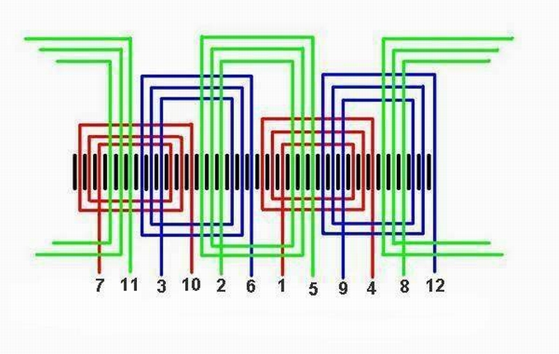
The most common winding being used today ( up to about 10 HP ) is a concentric winding, 4 pole, 36 stator slots, with a total of 6 groups of 3 coils per group, 18 coils in all. This winding having 2 coil groups per phase, produces 2 poles per coil group, and is connected in a consequent pole fashion.
Here is a lay out of the mentioned winding that corresponds to the connection diagram in the last photo.
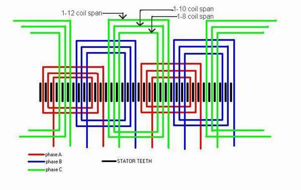
another diagram showing the winding lay out with phase markings and showing the lamination set.
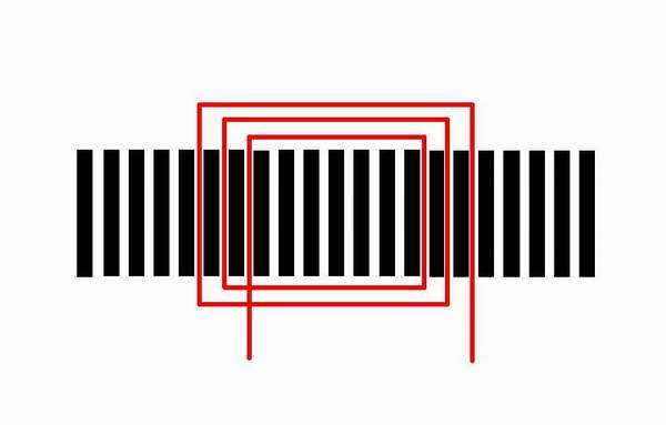
here is a diagram showing the lamination set layed out flat with one coil group installed
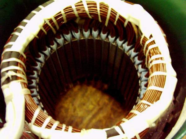
here is a picture of a completed winding i did on the 2 Hp showing the spans of the 12-10-8 winding. Note that only 3 leads have been brought out of this winding as it is designed to give cut in voltage of 14 volts using a 2 Delta connection at 200 rpm.
This is just the first part of a few posts into my diary that i hope you will enjoy.
zubbly
