Author Topic: Smartdrive alternator preliminary testing #1  (Read 6558 times)

0 Members and 1 Guest are viewing this topic.

commanda

  • Hero Member
  • *****
  • Posts: 731
Smartdrive alternator preliminary testing #1
« on: August 14, 2004, 02:35:35 AM »
I threw together a bearing carrier today, rough & ready it was. Too rough & ready it turns out. The balance is terrible. But I got some data none-the-less.


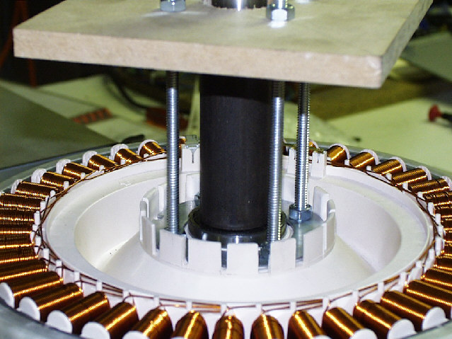
The first photo shows a close up of the clamp assembly. The problem lies in the piece of tube I used as a spacer between the two bearings. It's internal diameter is 27 mm, not 25 mm (which would fit snugly against the shaft). Also, the ends are hand finished, whereas they should be squared off in the lathe.


The next two photos show it sitting in the drill press, with a long aluminium bar used as a torque rod to stop the stationary bit turning. You can also see the two multimeters, and the jug I used as a dummy load.


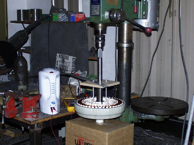
The drill press is a somewhat dilapidated 1/2 hp unit. It's slowest speed is 280 rpm, which I used. One winding on the alternator, that is, from the neutral point to one free end, gave 79 volts open circuit. I measured the frequency at 137 Hz, which leads me to believe the true rotational speed of the drill press is 293 rpm.


I then connected the jug, full of water, as a load. The dc resistance of the jug element was 27 ohms. I then measured the voltage from the alternator at 49.5 volts, and the current at 1.8 amps. This equates to a power output of 89 watts.


It also gives me an internal impedance of (79 - 49.5) / 1.8 = 16 ohms. Now, since the DC resistance of that winding is 6.5 ohms, this warrants further investigation.


First, I don't think I have the rotor bedded all the way in to the stator. Second, my currents and voltages might be out of phase (this actually makes things even worse if that is the case); although I believe the jug element would be mostly resistive. Repeating the test with the dual trace cro will clarify this.


I've yet to extrapolate this data to determine the best way to hook up my transformers, but I think the further testing mentioned above should be performed first.


However. Extrapolating the data so far, to get 900 watts out of this unit, I need 511 rpm. My target is between 750 & 1000 watts peak. By the way, the limiting factor in getting power out of any alternator is internal heat. I believe the F&P unit scores particularly well on this point, being open to the air on side. It's also relatively large.


Using blade calc with the following data

Blades = 3

TSR = 6

Blade Efficiency = 0.4

Blade radius = 2.5 metres

Wind velocity = 6 m/s


gives 1034 watts at 137 rpm


trying some different numbers

Blades = 3

TSR = 6

Blade Efficiency = 0.4

Blade radius = 1.4 metres

Wind velocity = 9 m/s


gives 1095 watts at 368 rpm


The pattern is obvious. You need a small diameter blade & high wind to get the power at the required rpm's.


The upshot of this is you get progressively lower outputs at slower winds.


Whilst I still have much testing and number crunching to do, my feeling is that the way to maximise output from these units lies in a Savonius rotor (lots of torque) with a geared-up drive to the F&P alternator.


Another by the way. Doing a maximum power transfer analysis at 280 rpm, Vo/c = 79, Impedace = 16 ohms, all 3 coils, gives 292 watts. Pretty close to the quoted 300 watts output from one of these units rigged as a hawt.

I really need more data at higher rpm's to pursue this further. I expect the open circuit voltage to be linearly proportional to rpm, but what about the internal inpedance. If it's relatively constant, short of cooking the windings, the sky's the limit.


More later.


Amanda


PostScript......

Last minute thought. If I inverted the whole assembly in the drill press, the imbalance would be that much less. Might try it tomorrow.

« Last Edit: August 14, 2004, 02:35:35 AM by (unknown) »

Flux

  • Super Hero Member Plus
  • *******
  • Posts: 6275
Re: Smartdrive alternator preliminary testing #1
« Reply #1 on: August 15, 2004, 02:01:38 AM »
Amanda


Just a thought on the impedance, I suspect those long poles cause a significant amount of leakage reactance.


If you can run it with a heavy load at different speeds you will probably find that higher speeds the current reaches a limit and remains virtually constant.

The turnover frequency will be where the resistance is equal to the inductive reactance.


If you are using a transformer it may not be a problem as you can keep the volts up and current down.


Flux

« Last Edit: August 15, 2004, 02:01:38 AM by Flux »

commanda

  • Hero Member
  • *****
  • Posts: 731
Re: Smartdrive alternator preliminary testing #1
« Reply #2 on: August 15, 2004, 03:20:18 AM »
I actually did some more testing today by inverting the assembly in the drill press. I think my imbalance problem is actually the bent shaft in the drill press.


I managed to get readings at 280, 350, and 450 rpm. I've found that the drill speed slows considerably when loading up the alternator, making the calculated internal impedance appear much worse than it really is.


I then went back & repeated the tests, this time measuring the ac frequency loaded & unloaded in an attempt to calculate the relative unloaded rpm & open circuit voltage which would correspond to the loaded frequency & rpm. I messed up somewhere, because my calculated open circuit voltage turns out to be less than the measured loaded voltage, which is clearly impossible. That's why I haven't written up todays results. I'll redo it all again tomorrow, this time using 3 meters so I can simultaneously record voltage, current, and frequency.


Amanda

« Last Edit: August 15, 2004, 03:20:18 AM by commanda »

domwild

  • Sr. Member
  • ****
  • Posts: 357
Re: Smartdrive alternator preliminary testing #1
« Reply #3 on: August 26, 2004, 09:31:16 PM »
Great shots! Many thanks! Am also playing with F&P motor. May be an Serial 60 (0.6mm wire in serial). As you know there are 100, 80 and 60 S, SP and P motors according to ecoinn of New Zealand. Judging by the kettle which we bought recently for AUS$9.00, you may be an Aussie too!??

« Last Edit: August 26, 2004, 09:31:16 PM by domwild »

commanda

  • Hero Member
  • *****
  • Posts: 731
Re: Smartdrive alternator preliminary testing #1
« Reply #4 on: August 26, 2004, 11:02:01 PM »
Yes I'm an Aussie. In Sydney. 2 acres at Wellingrove, near Glen Innes. Well, I'm paying it off, anyway. Then I'll build a house on it, and eventually retire there.


I believe there is also a 160 motor. Hope to be able to get on the lathe at work this weekend, time permitting, and do some more testing.


Amanda

« Last Edit: August 26, 2004, 11:02:01 PM by commanda »

domwild

  • Sr. Member
  • ****
  • Posts: 357
Re: Smartdrive alternator preliminary testing #1
« Reply #5 on: August 28, 2004, 01:40:53 AM »
Hi,

Apologies just in case I am preaching to the cognoscenty! You may not know the site

www.thebackshed.com/windmill   OR

www.watchtv.net/~rburmeister/smart.html


with interesting smartdrive info, especially ecoinnovation in NZ has power curves for the various models. Just measure your wire diameter and check if it is serial (S) or serial/parallel (SP) or parallel (P) and then you know the DC output at 24V from the ecoinnovation site.


Found a standard transformer in Jaycar catalog, 240 VAC to 0-15 and 0-30VAC, 8A for $AUS35.00 each or $105 total for three. Your Oatley idea of a toroid is interesting. Are they that much more efficient? Are they any cheaper? Wouldn't you need to go higher in your voltage than 18V??


The laser cut bits sold by thebackshed are very nice but a bit too pricey for me. I will get some bearings for the 25mm shaft and just mount it on a plate. How I connect a PVC prop to the spline shaft is still a mystery to me; I may have to file a plate to fit the splines.


Dominic Wild

Orange Grove near Perth, WA

« Last Edit: August 28, 2004, 01:40:53 AM by domwild »

commanda

  • Hero Member
  • *****
  • Posts: 731
Re: Smartdrive alternator preliminary testing #1
« Reply #6 on: August 28, 2004, 03:16:49 AM »
Dominic,


Yes, I've seen all those sites. I believe the ecoInnovation data on their site is with the coils re-wired for low voltage. Anyway, there's nothing like gathering your own data. Gives a better hands-on feel for what's what, if you know what I mean.


The 18 volts secondary is with 240 on the primary. It's turns ratio that's important. Although, I can put the primaries in parallel and make it 120:18. If I then put 240 on the primary, I'll get 36 volts on the secondary.


The Oatley toroids, with 2 primaries & 2 secondaries, gives more options with how it is connected.


In my setup, I can run the Fisher & Paykel as either star or delta.

The transformer primaries can be serial or parallel.

The transformer primaries, as a group of three, can be star or delta.

The transformer secondaries can be serial or parallel.

The transformer secondaries, as a group of three, can be star or delta; or wired to 3 individual bridge rectifiers.


So, total permutations is 2 * 2 * 2 * 2 * 3 = 48


Admittedly, some give the same end result, but I'm sure you get the idea.


The Oatley transformers were $25.00 each, so yes they're cheaper. Although freight to WA might put a dent in the difference. I work in the next street. Lucky, aren't I.


And yes, toroids are more efficient than the regular E-I lamination type transformers. Although the high-silicon used in audio coupling transformers is better than the regular mains type transformers.


Blades..... What about a round, flat plate, bolted to the stator, with the blades attached to that.


Amanda

« Last Edit: August 28, 2004, 03:16:49 AM by commanda »

domwild

  • Sr. Member
  • ****
  • Posts: 357
Re: Smartdrive alternator preliminary testing #1
« Reply #7 on: September 07, 2004, 12:04:24 AM »
Amanda,

Thanks for all that. Unlike you I do not have a black belt in electrickery and am wondering if you are going to post your MPPT so I can copy it?? A heating load can't go on straight away, so I need some sort of Piggot-style or your style LM2917 relay, perhaps one phase first to the load at lower RPM, then two phases and all three phases at even higher RPM.


Am tempted to buy Hornet carbon fibre props as they would stand the strong winds in Walpole (SW of WA) on my farmlet. Perhaps without furling.


How are you going to support your 6005 ball bearings? I could not find a bearing holder so far for the F&P bearings, only so-called pillow-block bearings as used in gokarts.


Cogging would mean a high startup torque is required. Does it need a six-bladed hornet or an equally large swept area? Have you thought of PVC props?


What sort of varnish or Araldite do you have in mind to stop the corrosion of the coils?


Is it worthwhile to switch between star and delta, if so then you have to have six cables coming down the top or six slip rings? Do you think a mercury switch attached to a flat blade into the wind could simply switch to delta at high wind? Or switch on my heating load?


Too many questions for you; this is a tall order - my apologies!


Dominic

« Last Edit: September 07, 2004, 12:04:24 AM by domwild »

commanda

  • Hero Member
  • *****
  • Posts: 731
Re: Smartdrive alternator preliminary testing #1
« Reply #8 on: September 07, 2004, 05:07:36 AM »
Black belt in electrickery, eh? Have to remember that one.

The MPPT will be posted as progress is made. Still kicking ideas around at the moment.

I've built the pwm to 2 phase converter to drive the IGBT's. I've got six big diodes, and some big capacitors (470 uF 400 volt) coming courtesy of eBay. I've got the switchmode transformer wound.


DANGER WILL ROBINSON. This thing will make 340 volts dc at 500 rpm. (Insert obligatory legal disclaimer here).


I built a 50 amp analog panel meter (see my diary). The voltage output from this will be used as input for the mppt.


Switching loads one phase at a time is not a good idea. Vibration.


Bearing holders. I work for a company with a mechanical workshop. Within reason, I can get anything made.


PVC blades. Not on a 300-500 watt setup. Not long-term anyway. Just my thoughts. I'm sure someone will have an opposite opinion.


Don't build a setup without furling. You will regret it eventually. Murphy's law hasn't been repealed yet.


Protection from the elements. Conformal coating. Comes in a spray can. We use it on our electronics (gas sensors) for coal mines.


With MPPT, star-delta switching becomes obsolete. Or, put your relays at the top of the tower. Then you only need 2 low power wires to fire the relays. You can hang a comparator off the output voltage (pin 5 I think) of the LM2917, with some hysteresis, to operate the relays.


Cogging. F & P's can be decogged. Somebody sent me the instructions & some photos.


I've still been unable to get at the lathe at work to do more testing on my F & P, due to the amount of work going through the workshop at the moment. And now we're moving house, so I'm somewhat pre-occupied with other matters at the moment. I'll probably be off the internet, from home at least, for several weeks.


Amanda

« Last Edit: September 07, 2004, 05:07:36 AM by commanda »

Nando

  • Hero Member
  • *****
  • Posts: 1058
Re: Smartdrive alternator preliminary testing #1
« Reply #9 on: April 16, 2005, 11:26:57 AM »
AMANDA:


REFERENCE:

>It also gives me an internal impedance of (79 - 49.5) / 1.8 = 16 ohms. Now, since >the DC resistance of that winding is 6.5 ohms, this warrants further investigation.


Reason for this difference is the Gap between the coil and the magnets that has as well a value that is dependent on the current flowing through the generator that in this case is 16-6.5 = 9.5 ohms ( magnetic).


All motors and generators do have such effect !!.


To generate 1000 watts you may need around 1000-1100 RPM , Michael Lawley ecoinn@paradise.net.nz is producing wind mills using the F & P motors and I think he offers 400 or 700 watts, I am not sure.


Dual F & P wind mills may require special arrangement to reduce the cogging dramatically if the motors are not de-cogged -- which may reduce the power somewhat, I do not know how much.


Regards


Nando

« Last Edit: April 16, 2005, 11:26:57 AM by Nando »