First a big thanks to all who replied to my posting asking for ideas for a DIY load sensor. You have given me quite a few ideas to work on.
Perhaps I should say now that although I have been tinkering with electronics for about 45 years now since I was a young child inspired by my fathers own electronic interests ( He built a TV from scrap radar equipment so that the family and neighbours could watch the Queens' coronation in 1953 ) my methods are mainly try it and see if it works. If it doesn't work play around with it till it does! I've never been a great fan of the theoretical side of things.
At the moment I am using a Statpower 800i inverter to power all my house lighting which consist of cfl's and strip flourescents converted to electronic ballasts. The inverter is run off a 12 volt 110 Ahr Leisure battery which at the moment is kept charged by two 80 Watt solar panels mounted on a homemade tracker. I intend to replace the one battery with 4 Trojan T105's wired as 24 volt as soon as funds allow. I have already got several 24 volt inverters that I bought cheap as faulty and repaired.
So at the moment power is precious and I can't afford to waste any leaving the inverter switched on all the time. The inverter is downstairs so tends to be left on all night when I go to bed so it's often on for 8 hours at a time when it's not needed. In common with most of the cheaper inverters the Prowatt has no load sensing 'Search' mode so I decided to try and devise a simple external solution to this that could be applied to any similar inverter.
Basically the circuit needs to see when a load across the inverter output is switched on and then switch the inverter on to supply the load. When the load is switched off, the circuit needs to switch off the inverter. Quite easy in theory but perhaps not so easy in practice.
Of course when the inverter is off there is no voltage across any load which is switched on and hence no current flow for the load sensor to 'sense',so we need to supply a 'sense' voltage across the output of the inverter to give enough current flow to be detected by the sensing circuit when a load is switched on. I decided to try 12 volts at first as it is a nice safe voltage to work with when you're experimenting.
I now needed a shunt of some sort to go in the output of the inverter to give an indication of current flow and a method of detecting said current flow.
I recently built an Amp Hour meter to the design of Frank Winter
(http://members.optusnet.com.au/frankwinter)
which uses a current sensing ic, the MAX472, to measure the current flow in and out of a battery bank. This chip has the useful feature that it has a 'sign' output which goes high when the current flow is in a particular direction. Ha Ha I thought, just the thing! Put the inputs of the chip across the shunt and use the sign output to operate a relay to switch the inverter on and off. A way of disconnecting the 12 volt sense voltage was also needed once the inverter was powered up so another relay was used for this.
The preliminary circuit is shown below. I will try and post a better drawing when I can suss out how to get a decent jpeg or pdf out of my PCB software.
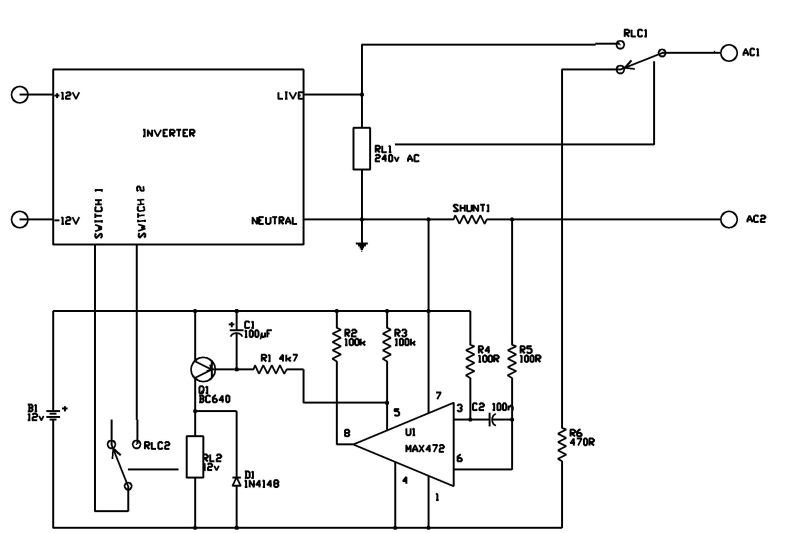
The Max472 is not fussy about the value of the shunt and in fact any old bit of wire will do! The circuit does not need to be calibrated so the resistance is unimportant. I used a 6 inch length of 1.5 mm cable in the test setup and this could probably be shorter. The only criteria is that it must be able to carry the total load on the inverter without a significant voltage drop. The leads from the shunt may need reversing if the sign output does not go high when a load is applied. The 12 volt sense voltage is applied through relay contact RLC1 which also isolates the output of the inverter.
When a current flows through the shunt the sign output of the MAX472 goes high which turns on Q1 and operates the relay RL2. The contacts are wired across the on/off switch of the inverter and so the inverter is switched on. Relay RL1 which has a 240 volt AC coil operates as soon as the inverter supplies AC, disconnects the 12 volt sensing voltage and connects the output of the inverter to the load. The shunt senses the current drawn by the load and relay RL2 remains operated. The current through the shunt is now AC and this causes the sign output of the MAX472 to turn on and off at the the AC frequency which would cause the relay RL2 to chatter. Capacitor C1 keeps Q1 turned on as the sign output turns on and off so the relay remains permanently operated.
When the load is switched off, current flow through the shunt ceases, the sign output of the MAX472 goes low and turns off Q1. Relay RL2 releases and switches off the inverter. Relay RL1 releases, disconnects the inverter output and re-connects the 12 volt sense voltage again ready for next time.
At the moment the sensing circuit is powered from a seperate battery but in the finished unit it will probably be fed from the main battery bank via an isolating DC to DC converter. The current draw at the moment is only 36 mA when switched and virtually nothing in search mode (0.06 mA) so it could even be operated from a seperate battery altogether.
That's the easy bit done. The problem now is to get it to work with cfl's ! These take no current at all with the 12 volt sense voltage so will not operate the unit. No problem I thought, just wire a resistor across each light fitting! Not that simple.
The MAX472 will operate on a current through the shunt of 1.8 mA (0.0018 Amps) which is equivalent to a load of about 0.02 Watts on 12 volts. In fact it's very sensitive (just like me!) This equates to a resistance across the 12 volts of about 6.8k. Unfortunately as soon as you put 230 volts across 6.8k it then takes about 0.034 Amps or nearly 8 Watts. Apart from needing high wattage resistors, there's all that wasted energy! What I need is a resistor with a positive voltage coefficient i.e it's resistance increases as the voltage increases and I don't think such an animal exists, at least I can't find any reference to anything suitable.
So that is the problem I'm working on now. I don't really want to increase the sensing voltage if I can help it as it works fine with resistive loads. One thought I had is to use inductors rather than resistors as they could have a low DC resistance but a high AC resistance e.g. miniature mains transformers and just use the primary winding. In theory a transformer would use no power if the secondary winding is not connected but obviously in practice this is not true. I could get them small enough to squeeze into the light fittings.
Another thing I'm working on is switching the inverter via the remote socket that a lot of inverters have. This would avoid wiring to the internal switch. This is not quite so simple though as the remotes are usually just a push button switch that toggles the inverter on and off via an internal flip-flop. I did get a circuit working to do this but a problem is that it could get 'out of sync' with the load being switched so that the inverter was on when it should have been off and vice versa.
