After much head scratching and scribbling on bits of paper I decided that sticking with a DC sensing voltage was going to make life very difficult. Some of you had suggested using an AC voltage instead so I decided to give this a try. In theory a simple capacitor across the cfl's should provide a current flow across the shunt to activate the MAX472.
A simple square wave oscillator was built using a 555 timer chip and the output fed to the inverter output relay. The 555 runs at about 250 Hz.
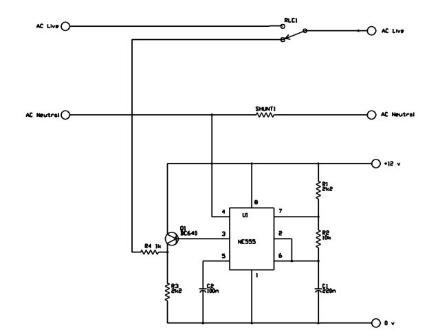
By playing about with capacitor values I found that the smallest capacitor to reliably operate the sensor was 330n. Eliminating the 1k resistor in the oscillator output enabled a 220n to work but I wanted to keep the resistor to isolate the oscillator in case of shorts etc. I could probably replace it with another capacitor which may be better. Note that these capacitors must be X2 rated i.e. they must have a working voltage of at least 250 volts AC. Current consumption has obviously increased due to the addition of the 555 but is still pretty negligible- 46 mA switched and 18 mA in search mode.
At the moment the circuit seems to be working OK in the test setup so now it's out with the PCB equipment and make a proper board for it. It also needs a DC to DC converter to provide an isolated supply from the inverter battery but that should not be a problem.
