I spent today mounting the PCB and the inverter output relay in a nice plastic box along with a connector block for wiring it in circuit.
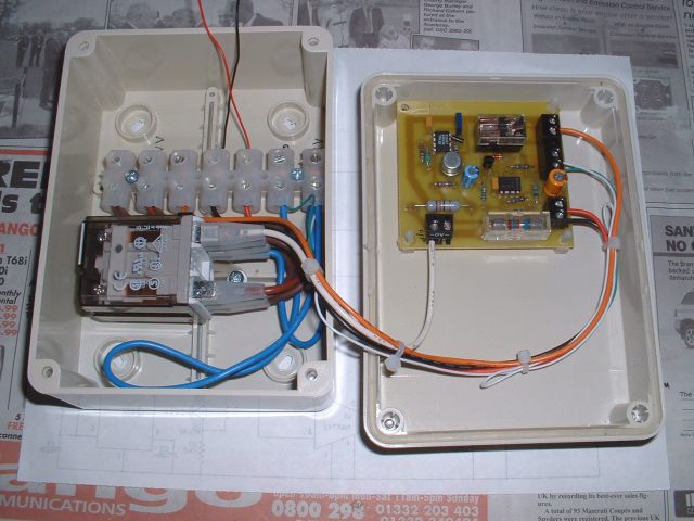
The loop of blue wire is the shunt in the neutral output of the inverter to sense the load.
After doing all this I thought I had better test it again before I wired it into the main inverter. Surprise, surprise it didn't work! It worked before I put it in the box so I must have done something stupid with the wiring. I checked all the connections and could not find anything wrong so I wired the PCB up to my original test inverter along with a lamp and the original shunt. It now worked! My immediate thought was that the new shunt I had made for the box was too short and not dropping sufficient voltage to activate the MAX472 so I extended it and tried again. Still didn't work. I just could not see why not. The only difference between the two setups was that the wiring from the MAX472 to the original shunt was in thin stranded wire ( to fit in the breadboard I had built the prototype on ) whereas the wiring in the new layout was much thicker. So I replaced the thick wire with a piece of the thin and it then worked. After much head scratching I realised that one of the wires from the shunt to pin 3 of the MAX472 was acting as an extra shunt in series with the main shunt and giving a larger voltage drop across the sensing inputs of the chip. Although this did not affect the working of the circuit once the load had switched on ( as the main shunt still dropped sufficient voltage to hold the circuit operated once the inverter was switched on ) it affected the initial sensing current created by the 12 volts AC from the 555 oscillator.
I could have got around this by increasing the length of the new shunt even more and hence increasing the resistance but I didn't particularly want to do this because of the losses this would cause. After pondering about this for a bit I realised that having this extra shunt in the wiring to the sensor PCB was not really a problem. None of the AC load current passed through it anyway. The only snag was that the sensing circuit would have to be fed from a supply isolated from the inverter battery to avoid problems caused by this extra resistance. This was no big deal as I could either build a small DC to DC converter or just power it from a seperate battery. I have quite a few small SLA's that I could use.
Having sorted all this out I put it all back together, mounted the box under the inverter and connected it up to the inverter and consumer unit and a small 12 volt SLA that I had lying around. Now came the moment of truth! I replaced one of the cfl's that I use for lighting with a 60 watt incandescent and switched it on. The inverter switched on and there was light! I switched off the light and the inverter switched off as well. Success!!
The thing to do then was fit the capacitors across all the cfl light fittings so that these would operate as well. Unfortunately I only had two suitable X2 capacitors to hand so I could only do two light fittings. I used 0.33uf which seems to work OK and are not too big to fit inside ceiling roses etc. After fitting the first one I switched on and it worked perfectly. The second however fired up but kept going on and off instead of staying on. I guessed that this was because the current draw was not quite enough to hold the load sensor operated. This particular light is at the end of the lighting loop and probably has slightly more resistance than the rest. This was solved by increasing the length of the main shunt by a couple of inches and it then worked fine.
Then disaster struck and it all suddenly stopped working! Investigation showed that the output transistor in the 555 oscillator had blown resulting in no output. I surmised that it had probably succumbed to a voltage spike or something fed back through the capacitor that feeds the 12 volts AC to the inverter output relay. So I replaced the transistor and put a voltage limiter consisting of two 12 volt zener diodes across the transistor hoping that this will stop this happening again. I also put a 100R resistor in series with the capacitor to limit the current.
It's now working again so we'll see how it holds up.
I'll try and post the latest version of the circuit if it turns out:
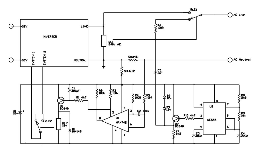
Shunt 2 is the extra shunt created by the wiring to the PCB. Both shunts are very low resistance, so low that I can't measure them with my meter.
D2 and D3 are the two back to back zeners to protect (hopefully!) Q2
The main shunt 1 needs to be of sufficient resistance to keep the sensing circuit operated with the smallest load on the inverter which in my case is an 11 Watt cfl. Shunt 1 plus Shunt 2 need to be of sufficient resistance to activate the circuit initially to switch the inverter on.
One or two problems still need to be ironed out. The inverter output relay RL1 buzzes slightly when the inverter is on, probably due to the MSW, and it chatters briefly when the inverter switches off. This may be what originally blew Q2. It may be caused by the way the AC output of the inverter decays when it switches off. The circuit needs a power supply although the small SLA I am using at the moment is simple and will probably last for months before recharging.
One interesting thing I found was that the three flourescent fittings I have fitted with electronic ballasts operate the circuit without having capacitors fitted which saves a bit of work.
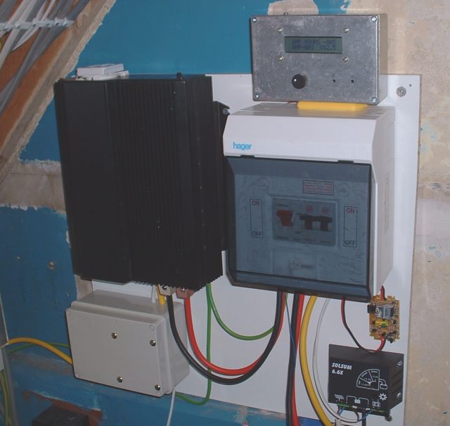
Piccy of the inverter etc . The grey diecast box is the Amp Hour meter which reads the amp hours in and out of the battery. This gave me the original idea to use the MAX472