Author Topic: Alternator Conversion  (Read 1481 times)

0 Members and 1 Guest are viewing this topic.

jimovonz

  • Sr. Member
  • ****
  • Posts: 339
Alternator Conversion
« on: October 19, 2004, 05:44:18 AM »
Finally managed to make some progress! This alternator started out as a 24V, 140A unit fitter to a Kawasaki 80 Wheel Loader. It has a 12 pole rotor just under 6" in diameter and is 8" diameter overall. There are 18 overlapped coils made up of 6 x 3 phases in the stator. Each phase is made up of two conductors approx AWG 16 wound in parallel. In an attempt to make it more suitable for use in a wind genny I have made some modifications. I have fitted 24 neos to the rotor, tapped the windings, removed the internal rectifier and re-assembled. I have retained the brushes and field windings.


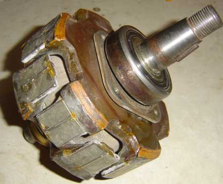
Rotor with mags fitted:


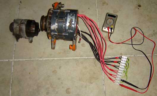
Assembled Alt showing tapped windings connected in series 'Y'. Note the 12V, 60A alt for comparison


Preliminary testing is showing some promising results. As expected, adding the mags has produced a cogging effect, however this is less than I get from one of my standard F&P smartdrive motors (probably closer to the 'de-cogged' version). With the windings connected in a series 'Y' and not using the field coil, I can get about 10Vac between two phases by giving the pulley a hard turn. If I maintain a constant 1rev/sec (very approx by hand!) I get about 2Vac. This indicates a 24Vdc cut-in speed of around 500rpm.

I was initially unsure as to what effect the use of the field windings might have in conjunction with the permanent mags. I was hoping that I would be able to boost and/or retard the flux that the coils see so as to boost output and/or reduce cogging on startup. I connected the field coil up to my bench supply and supplied it with 24V (~1A). This noticably increased the 'cogging' effect. Giving the pulley a hard turn now produces aprox 15Vac, a 50% increase! It is not possible to maintain 1rev/sec because of the increased cogging, but 2rev/sec gives 5-6Vac, once again approx 50% improvement and closer to a 300rpm cuttin. Reversing the field current drastically reduced the cogging effect - it is still there but barely noticable! With the field reversed the most I can get by giving the pulley a hard pull is 2Vac.

Ultimately I am looking for 2+kW at 1000 alternator rpm and intend to use 1:3 gearing for my turbine. I realise that this 'testing' is very approximate but theyes give me some hope - enough at least to make sure I get a proper test rig set up this weekend so I can load this unit up and get some accurate results.

« Last Edit: October 19, 2004, 05:44:18 AM by (unknown) »

TomW

  • Super Hero Member Plus
  • *******
  • Posts: 5130
  • Country: us
Re: Alternator Conversion
« Reply #1 on: October 19, 2004, 07:19:26 AM »
Jim;


Pretty interesting stuff there. The information on the effect of energizing the field in both directions is interesting in itself and has made me think about why its doing that.


A proper test rig may give much interesting information especially if you decide to test various field currents which may show some sweet spot where cogging versus output power work the best. Next time i see you on IRC I will have a few questions and ideas for testing and how to get set up to do it if you need it.


Cheers.


TomW

« Last Edit: October 19, 2004, 07:19:26 AM by TomW »

hiker

  • Hero Member
  • *****
  • Posts: 1661
  • BIG DOG
Re: Alternator Conversion
« Reply #2 on: October 21, 2004, 02:11:31 AM »
just curious- do the mags on each leg of the rotor have the same pole up?

i noticed you are using two mags per leg.fun to glue right,,,,,

i used some big old seagate harddrive mags on mine ,had to break the mags in half

but they still worked fine. it was a 12volt auto alt..worked fine but needed rpms

for decent power output..

« Last Edit: October 21, 2004, 02:11:31 AM by hiker »
WILD in ALASKA

jimovonz

  • Sr. Member
  • ****
  • Posts: 339
Re: Alternator Conversion
« Reply #3 on: October 21, 2004, 12:34:36 PM »
Yep, the two magnets on each leg have their poles facing the same way...Yep they were fun to glue down... In this orientation the paired magnets repel each other sideways, making them very hard to hold together. I used superglue to hold the magnets in place - you will probably notice the skin from the surface of my fingers still on the magnets in the pics :-). I then slathered the whole lot in expoy and baked it in the oven for a few hours.

As I have retained the use of the field windings, as well as being able to rewire the two parallel stator windings in serial, I am fairly confident that I have managed to shift the power output curve lower down the rpm range - just how much I won't know till I do some testing.

Did you manage to do anything useful with your converted alt?

« Last Edit: October 21, 2004, 12:34:36 PM by jimovonz »

hiker

  • Hero Member
  • *****
  • Posts: 1661
  • BIG DOG
Re: Alternator Conversion
« Reply #4 on: October 21, 2004, 12:44:25 PM »
sence i pay one flat rate for water[use as much as i want]--i was thinking of makin

a pelton wheel for it and run it off a garden hose with some  small high pressure

nozzels--i could run it 24/7--even if the amp output is low it should make a good

charger............
« Last Edit: October 21, 2004, 12:44:25 PM by hiker »
WILD in ALASKA

jimovonz

  • Sr. Member
  • ****
  • Posts: 339
Re: Alternator Conversion
« Reply #5 on: October 21, 2004, 01:38:10 PM »
Ahhhh.... Not exactly 'Renewable Energy' tho aye? However I'm sure there are quite a few folk out there that will happily look the other way while you rob the utility company of energy! (which would essentially be comming from their pumps...)
« Last Edit: October 21, 2004, 01:38:10 PM by jimovonz »

monte350c

  • Full Member
  • ***
  • Posts: 228
Re: Alternator Conversion
« Reply #6 on: October 21, 2004, 04:05:02 PM »
Hi jimovonz,


Nice job, I have one quick question - where did you get those nice arc shaped magnets??


This looks like an interesting way to go, you should have a lot of control over the alternator and its output with both the magnets and the field coil available...


Ted.

« Last Edit: October 21, 2004, 04:05:02 PM by monte350c »

jimovonz

  • Sr. Member
  • ****
  • Posts: 339
Re: Alternator Conversion
« Reply #7 on: October 22, 2004, 02:00:02 AM »
Thank you Ted,

The magnets I have used are not curved at all. I have used two 1"x1/2"x1/4" neos on each pole side by side with like poles facing in the same direction. Although the use of the two magnets in this manner makes fixing them a problem (as they repell each other sideways), it does allow me to follow the curve of stator more closely (reduce the air gap ~ 1mm) After placing the magnets with superglue, I covered the magnets on all sides with expoy and later sanded the rotor down. This is what gives the magnets the rounded look.
« Last Edit: October 22, 2004, 02:00:02 AM by jimovonz »

oztules

  • Hero Member
  • *****
  • Posts: 1477
  • Country: aq
  • Village idiot
Re: Alternator Conversion
« Reply #8 on: February 27, 2006, 09:45:50 PM »
Well well well, Interesting use of field dampening and field accentuating. This leaves the way open to do zubbly conversions, but by building a new rotor of like design to this, we could mppt without buck converters, and better match the flux for any given rev. Most interesting Hybrid design... rat cunning  ... i like it.........oztules
« Last Edit: February 27, 2006, 09:45:50 PM by oztules »
Flinders Island Australia