I salvaged this small single phase induction motor out of a faulty beer cellar cooler that I repaired a few months ago and thought it may come in handy to make a small PMA.The bearings had seized and the windings had overheated. The nameplate was illegible but I would guess it is about 1/10 HP. Reading Zubblys' excellent three part series on the conversion process inspired me to get the tools out and have a go.
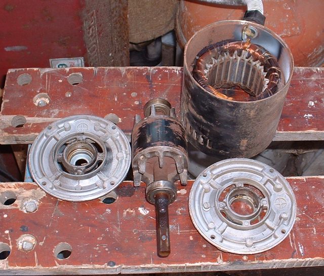
The rotor is only 2 1/2 inches in diameter by 1 7/8 inches long but I thought it would be ok for a first attempt. It should produce a 100 Watts or so.
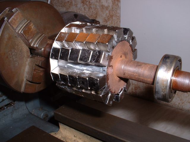
I decided to use 3/8 inch square neos for the conversion as this meant 5 would fit across the rotor exactly and offsetting each one slightly as they went across the rotor would skew the magnet poles to reduce cogging. Also making the poles of smaller magnets rather than one large one would mean a smaller airgap between the magnets and the stator. The rotor was mounted in the lathe and turned down in diameter to allow the magnets to be glued to the outside.
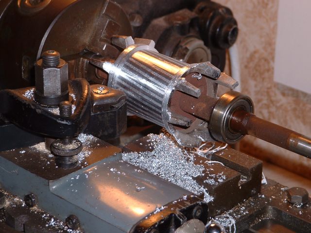
I had hoped to keep the aluminium fins on each end to help cooling but unfortunately I had to turn them off to get down to the correct diameter.
The original stator has 24 slots. I wanted the finished alternator to be three phase so I decided on an arrangement of two coil groups per phase. Each coil group will consist of two concentric coils, the inner coil spanning 6 slots and the outer coil 8 slots. This gives a 4 pole magnet rotor, N S N S.
Measuring the required span of each pole against the stator teeth gave a width which could be nicely made up of three magnets with a slight gap between each one on the surface of the rotor.
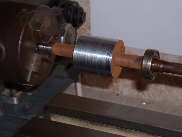
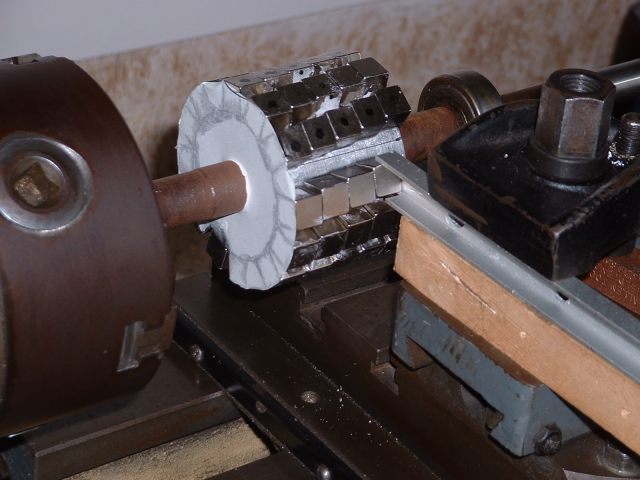
A disc of paper was marked out to give the correct spacing of the end magnets and this was then glued to the end of the rotor. The end magnets were then put on the rotor and held with superglue. So far so good. I then started on the second row. This was when the fun started as of course the adjacent magnets in each pole have the same polarity and repel each other fiercely! They have to be pushed against each other and held there whilst the glue sets. I eventually got this sorted by clamping the magnets in place with a piece of aluminium channel held in the toolpost. The magnets were put on the rotor, pushed into place using the lathe saddle, and then superglued. This procedure got harder and harder to do as the number of magnets increased but I eventually got the last one in place! Each row of magnets was offset slightly from its neighbour to give the skewing effect as mentioned previously.
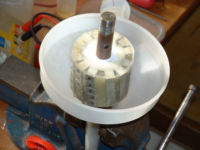
The black dots are to mark the poles of the magnets.
A strip of tape was wrapped around the outside of the magnets and one end taped over. The whole rotor was then stood vertically and two part epoxy resin poured into the gaps to encapsulate the whole assembly and glue the magnets firmly in place. The resin I used was quite thick and I had to keep poking a piece of wire down the gaps to release trapped air bubbles. The resin eventually filled all the gaps nicely though.
To work out the number of turns per coil I would need to get the required output, I followed Zubblys' method of winding a test coil, assembling the alternator, and then spinning it in the lathe and measuring the output. I used just a single phase rather than all three and wound the test coils with 20 turns to get a higher output.
Getting the rotor into the stator during assembly was a real struggle due to the attraction of the magnets and I think some sort of thin tube to act as a guide would be a great help. If this was thin enough and of a suitable diameter it could be pushed into the stator and the rotor slid down the inside to prevent any damage. Once the rotor was inside the stator the tube could be pulled out.
That's where the conversion has stopped at the moment as I'm re-arranging and tidying up the workshop to make some room to work in. Hopefully the coils will be wound and the conversion finished in the very near future. I'm looking forward to see what results I get from it.
John
