This is a quick story about progress so far on a motor conversion I started a couple of weeks ago.
I was in Princess Auto and noticed a 1.5 hp, 4 pole induction motor for a very reasonable price - I think it was about $200 including taxes.
It's a 115 / 230 volt, 14 / 8 amp unit.
I took it home, wired it up, and plugged it just to make sure it worked as a motor.
Next, the old rotor came out. I had a new one made at the machine shop and mounted the magnets using an approximate 1 slot skew between the sets. There's 2 wide per pole and 3 sets down the rotor. I had a bunch of pics of that stage, but I think I erased them off the camera before they got transferred to the PC, because I can't find them anywhere. I'll take more when I take it apart again.
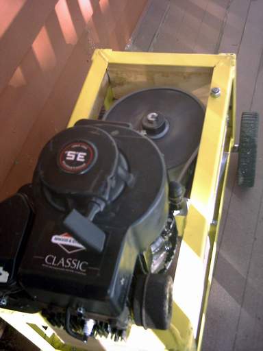
In my last diary, I mentioned the B&S powered unit I put together for testing things. This is the first real item to be tested on it.
I didn't rewind this motor, and the goal is to use the electricity for heating purposes, and make a wind turbine to drive it.
I didn't really have any numbers on this one, so I decided to see what it would do at around 600 rpm. I already had a 5.75" cast iron pulley on the bottom of the motor - which was nice since it acted like a flywheel which this variety of Briggs needs to run correctly. The problem was if I wanted 600 rpm out of it, it would need a jackshaft, or a 25" pulley to work with the one on the motor.
So instead I got a couple of chain sprockets, weld-on hubs, and a length of chain. All for about $40 which is a lot less than the jackshaft idea would have been.
The sprocket on the motor has 16 teeth, and the one on the converted induction motor has 72 which means when the Briggs is doing 3000 rpm the alternator will be doing 667 rpm which is about what I was looking for.
I'm no expert when it comes to chain, but I don't feel too comfortable with a horizontally oriented installation like this. If it developed any slack, it would almost certainly jump off the drive sprocket. I installed shields all the way around the frame in case it broke or came loose etc. And this unit is only to test.
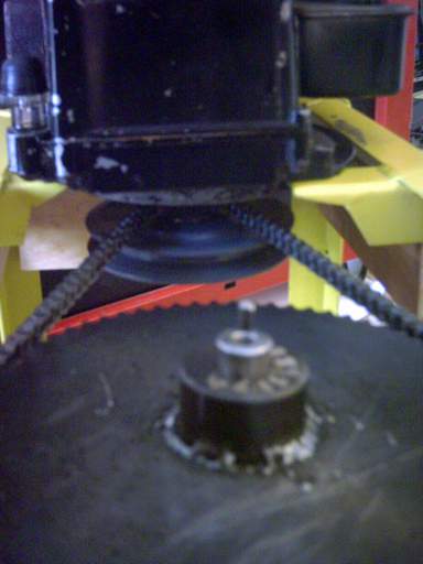
Here's a pic of the motor driving the converted induction motor:
Actually it runs very smoothly and there's not much vibration at all.
For this run I started with a single 100 watt light bulb, and let it run for about 15 minutes. The alternator was stone cold as you would predict.
Then another run at 350 watts, also for 15 minutes. Still no detectable temperature rise in the alternator.
Finally, 600 watts for 30 minutes. At the end of the 30 minute run, the case of the alternator was just detectably warm - I would guess about 95 degrees F or so.
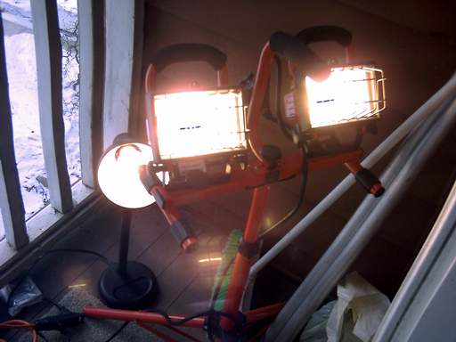
The lights are at full brightness. The halogen work lamp actually looked pretty much like it was running on grid power, but the 100 watt bulb was flickering quite a bit. Not surprising - we're only at 20 hertz or so!
Here's a pic of the output volts:
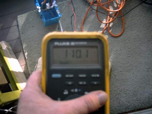
It pretty much stayed right around 110 VAC for the whole test. There was a very minor drop in volts per rpm from unloaded to 600 watt load.
The rest of the numbers: 21 hertz, 654 rpm, 600 watts, 110 VAC, 5.5 amps.
The amps are calculated since I don't have a good way to measure AC amps.
This test was done with the motor wired as it would be for 230 volt operation.
So the amp limit per the nameplate would be 8 amps or 880 watts at 110 volts. The 600 watts on the test would be 5.5 amps.
Next I plan to rewire it for 115 volt operation, spin it to 1,500 rpm which should be around 50 hertz and about 115 volts. At 14 amps this will be close to 2kw if all goes well.
More fun!
Ted.
