Author Topic: More F & P testing  (Read 1424 times)

0 Members and 1 Guest are viewing this topic.

commanda

  • Hero Member
  • *****
  • Posts: 731
More F & P testing
« on: April 11, 2005, 01:34:05 AM »
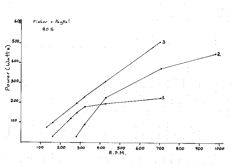
This graph shows the results of much testing.


There's a larger & more readable version

here


Curves 1 & 2 are for the toroidal transformers.

Curve 3 is rectified to dc directly.


The F & P in question is wound with 0.8 mm wire.

The windings are left stock.

It is not de-cogged.


Curve 1:

F & P in star.

Toroidal Primaries in Delta.

Toroidal Secondaries individually rectified.

Toroidal ratio 120:18.


Curve 2:

F & P in star.

Toroidal Primaries in Star.

Toroidal Secondaries individually rectified.

Toroidal ratio 120:18.


Curve 3:

F & P in star below 400 rpm.

F & P in delta above 400 rpm.

3 phase rectifier feeding 2 x 470uF/400volt caps in series.

The load was 3 jug elements in series, giving 35, 70, 105 ohms.

At each rpm, 3 tests were done with 3 different loads.

The best result was used to graph the power.

A number of results shows the power peaking at the 70 ohm load,

and being less with 35 & 105 ohms. This is what we would expect

from maximum power transfer theorem.

This curve also does not allow for any inefficiencies in the

proposed dc-dc converter.


Conclusions:

The toroidal transformers achieve a result which is an acceptable

percentage of the theoretical maximum power recoverable, consistent

with being cheap, and simple to implement. Although the star/delta

switch adds some complexity. The savings in heavy cable, if the generator

is any appreciable distance from the batteries, should make this an

 attractive proposition. The graphs show the power decreasing with

frequency, though operating at above 700 rpm is not normally a very

common occurrence. This is probably transformer losses.


The formerly proposed dc-dc converter, probably wouldn't achieve a return

commensurate with the effort required, except in perhaps 3 instances;

first: if the blade power at low rpm was less than the generator power,

causing the blades to not pick up speed easily.


second: using 2 F&P's on one shaft. The dc-dc converter vs 6 toroids, may

become an attractive proposition.


third: in an area with constant high winds, where operation above 500 rpm

is the norm.


Amanda

« Last Edit: April 11, 2005, 01:34:05 AM by (unknown) »

domwild

  • Sr. Member
  • ****
  • Posts: 357
Re: More F & P testing
« Reply #1 on: April 10, 2005, 08:33:10 PM »
Amanda,


Thanks for that. Very interesting, very professional presentation, if I may say so!

Any delta figures as yet?

What sort of a prop was used or did you use the lathe at work?


Regards,

« Last Edit: April 10, 2005, 08:33:10 PM by domwild »

domwild

  • Sr. Member
  • ****
  • Posts: 357
Re: More F & P testing
« Reply #2 on: April 10, 2005, 08:35:52 PM »
Forget the previous post, Amanda. Did not read your post properly re star/delta. Still would like to know the prop, I hope I did not overlook that one!
« Last Edit: April 10, 2005, 08:35:52 PM by domwild »

commanda

  • Hero Member
  • *****
  • Posts: 731
Re: More F & P testing
« Reply #3 on: April 10, 2005, 09:01:01 PM »
This is strictly alternator testing, done in a large drill press.


Amanda

« Last Edit: April 10, 2005, 09:01:01 PM by commanda »

solarbbq

  • Newbie
  • *
  • Posts: 15
Re: More F & P testing
« Reply #4 on: April 12, 2005, 07:09:23 AM »
have you posted any voltage results for different rpm?

« Last Edit: April 12, 2005, 07:09:23 AM by solarbbq »

commanda

  • Hero Member
  • *****
  • Posts: 731
Re: More F & P testing
« Reply #5 on: April 13, 2005, 09:34:48 PM »
Check my diary. The open-circuit volts is linear with rpm. For the 80S model I have, it's 0.28 volts/rpm in delta, and 0.48 volts/rpm in star.


My first objective with these things is to run them at high voltage, eliminating line losses from the alternator to the house.


My second objective is to achieve maximum power transfer at all rpm's, maximising the energy yield. To do this I'm building a dc-dc converter, with a controller which will change the current to suit the rpm.


The interesting point from the graph I posted; the max power is a linear function of rpm. Assuming a constant battery voltage, the charge current is now linear with rpm. So we can use the dc output voltage from a tacho as the control input, and the dc output voltage from my ammeter as the feedback signal. We can build a max power point controller for the F&P's with a couple of op-amps, and a simple variable-frequency buck switchmode converter.


Amanda

« Last Edit: April 13, 2005, 09:34:48 PM by commanda »

solarbbq

  • Newbie
  • *
  • Posts: 15
Re: More F & P testing
« Reply #6 on: April 15, 2005, 01:10:10 AM »
thanks for that,

so say the windgen blades are hitting 200rpm then the voltage output would be:

delta o.28* 200=56v

star 0.48* 200=96

so a star config. will be best for transmission to house?

is your 80s wired in series or have you rewired to parallel?

just an off the side comment here, there is a new electric bike hub motor by company called wavecrest, it is very similar indeed to the fisher/paykel motors. They have star/delta hall effect sensors (3 for delta stator and 3 for start), hitting a switch converts your hub motor into a high torque at low speed or a low torque at high speed motor.

As far as  I can tell they have 2 stators in parallel, maybe possible to do this for a windgennie? one stator for star, one for delta on same axle????

thanks for posting the volts

« Last Edit: April 15, 2005, 01:10:10 AM by solarbbq »

commanda

  • Hero Member
  • *****
  • Posts: 731
Re: More F & P testing
« Reply #7 on: April 15, 2005, 03:05:58 AM »
so say the windgen blades are hitting 200rpm then the voltage output would be:

delta o.28* 200=56v

star 0.48* 200=96

so a star config. will be best for transmission to house?


This is correct. That's open circuit (no load) volts ac rms.

Just be careful, it can make lethal voltages at high rpm. Rectified and filtered, it will make 700 volts dc at 1000 rpm. 1000 rpm * 0.48 volts/rpm * sqrt(2).


so a star config. will be best for transmission to house?

simplistically, yes.


is your 80s wired in series or have you rewired to parallel?

It's series. Completely un-modified. Not even de-cogged (yet).


Like I've said before, I'm working on 2 different approaches.

The first, the F&P stays in star. 3 toroids, 120:18 250 va. Switch the primaries from delta to star at 400 rpm. Rectify the secondaries seperately with 3 bridges. This gives the best of curves 1 & 2 in the graph.


The second approach uses a dc-dc converter to achieve maximum power transfer. This will put us on curve 3 in the graph, ignoring losses in the dc-dc converter. I've actually nutted out the design in my head. Just got to build a couple of other pre-requisites first before implementing it.


email me off-list (alwynne at tpg dot com dot au) if you really want a treatise on maximum power transfer and how to implement it with the F&P's.


Amanda

« Last Edit: April 15, 2005, 03:05:58 AM by commanda »

richhagen

  • Hero Member
  • *****
  • Posts: 1599
  • Country: us
Re: More F & P testing
« Reply #8 on: April 17, 2005, 11:31:30 AM »
Nice stats, I'm wondering, since I'm no transformer expert, since the efficiency of the Toroidal transformers drops considerably at higher frequency, Is the loss in power showing up as heat in the transformer, or is the loading on the rotor decreasing.  Second, is either location of loss a cause for concern for operation in sustained high winds due to cooking the transformer, or overspeeding of the blade.  Rich
« Last Edit: April 17, 2005, 11:31:30 AM by richhagen »
A Joule saved is a Joule made!

commanda

  • Hero Member
  • *****
  • Posts: 731
Re: More F & P testing
« Reply #9 on: April 17, 2005, 03:12:01 PM »
These transformer's I'm using are 250 VA each, so they're pretty big. I haven't run it for long, but didn't notice any heat at all. I'm only using one old car battery at the moment, and the shaft tends to work loose in the chuck of the drill press.


Amanda

« Last Edit: April 17, 2005, 03:12:01 PM by commanda »