INDUCTION GENERATOR:
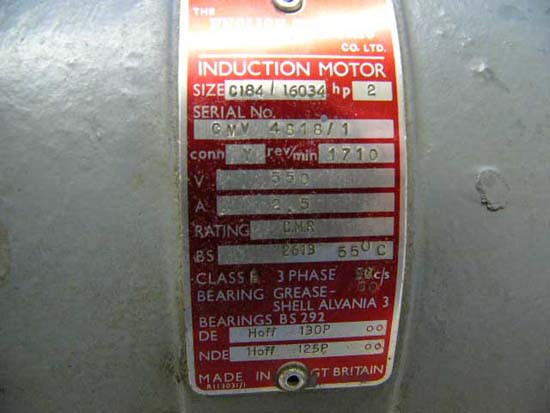
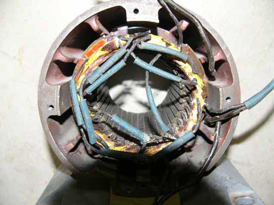
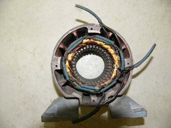
A friend as a favour gave me a 2hp 3-phase 550 volt 2.5 amp 1710 rpm 3 lead wye connection "English Electric" motor.
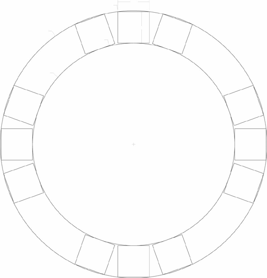
It is a 36-slot stator with a span of 6 (1-8).Experts please confirm!!
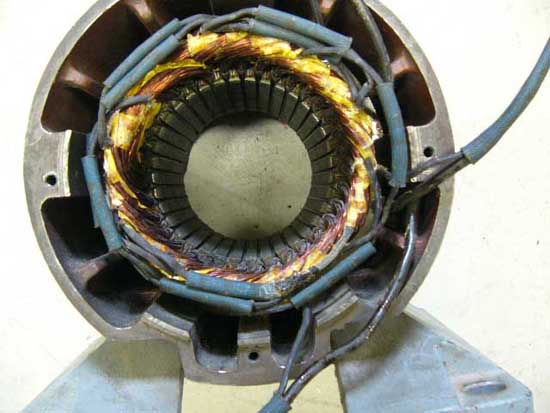
The stator bore is 3.250in. The rotor was 3.230 in dia * 4.0 inches long. Internally there are 9 connections, 1 wye, and 3 leads out, 22 gauge .025in wire .
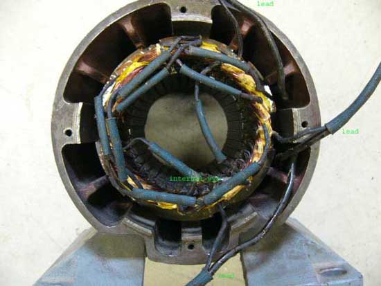
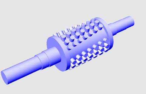
There are 15 ohms resistance between each phase. I modelled the rotor and magnets in Rhino software.
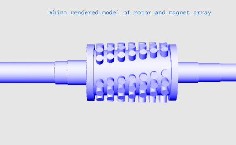
Since I have access to a lathe I turned the rotor dia to 2.448 to accept 3/8 * 3/8 neos. This is a smaller dia than 3.230-.750 = 2.480 because of the dia of the magnets at the radius of the rotor.
I turned the aluminum fins down to accept an ABS pipe as a location guide "cage" for the magnet spacing.
I then turned the ABS pipe O.D. to the original dia of the rotor 3.230.I decided to go with 3 rows of 7 magnets by 4 poles for a total of 84 magnets which I purchased from
http://www.wondermagnet.com. I calculated the helix angle and pitch for spacing the magnets. I made the helix the same direction as the lams in the rotor. I had the holes drilled in a cnc mill at work in off hours in the "A" axis. Total time was 25 min including set-up. If I need to change spacing or magnet size I may have to do a layout version a la Zubbly's method as our off shift was eliminated! I then added the magnets to the rotor and ABS "cage" in N S N S poles (21 neo mags/pole).
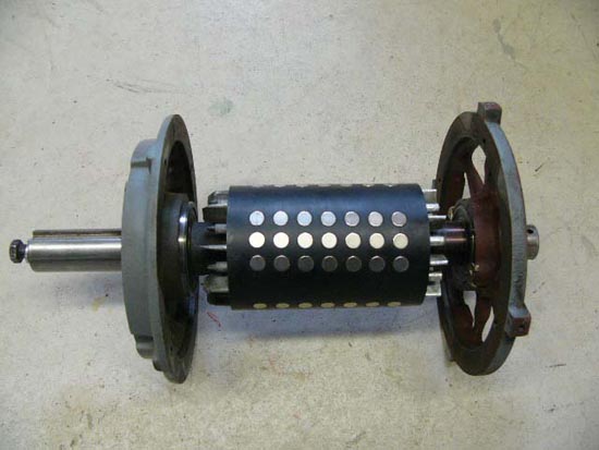
I have not yet permanently secured the mags in place opting to let them be held in by their magnetic power during the testing. I then reassembled the motor and there is no noticeable cogging affect as the rotor turns freely by hand. Later if magnet size is adequate I will drill some holes thru the abs pipe at the bottom and inject some Premium PL and have excess squeeze out thru holes drilled at the top. I will have 7 hose gear clamps around the diameter so mags will not get forced out as the adhesive cures. Hope it works, even though mags are free on the shaft I can not remove them unless I cut the abs cage open. I tried 1 mag on top of a mag on the rotor to see if I can remove it but no luck!!
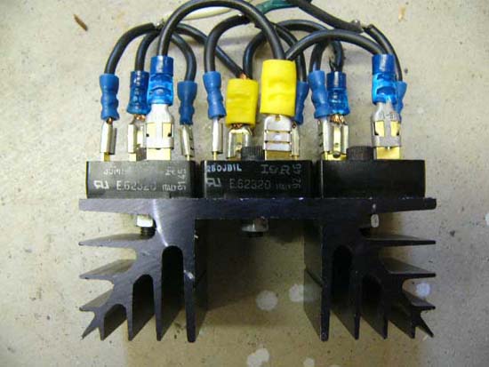
To rectify the 3 phase output I used 3 bridge rectifiers 250JB1L 25A 100V bolted & pasted to a heat sink. The 2 ac inputs on each rectifier was "bridged" with a wire and each phase from the motor attached to the 2 ac "bridged inputs .
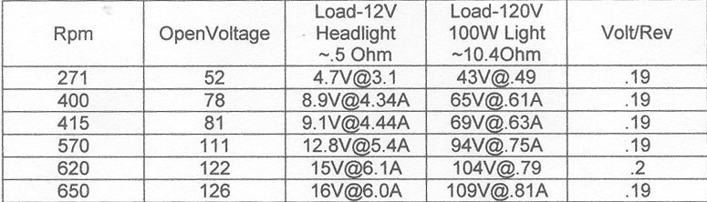
For testing I used my 16 speed drill press. The initial volt/rev was not linear, so I knew the speed chart on the drill-press was not accurate. After a search on this board, I found a cheap alternative tachometer made from a bicycle speedometer. Mathematically 1 km x 1000 m / km x 1000 mm / m x .1 [accuracy of digital speedo ie .1 km/h] / 60 = 1666.6 mm calculated circumference to be preset in speedo. Calibrating it to a cnc mill with known rpm I had to adjust the circumference to 1659 mm. Testing the drill-press with the speedo-tach confirmed the speed chart showing belt position was inaccurate. 250 rpm = actual 271; 340 = 415 ; 390 = 400 ; 510 = 620 ; 600 = 570 ; 650 = 650 . The speedo-tach reads 32.5 km/h as 325 rpm. Above 600 rpm it loses 3 digit accuracy ie 63km/h = 635 rpm, it starts to slip above 1000 rpm. Very accurate for windmill rpms.
Drill press test results.
I now have to get directions ( ZUBBLY!! ) on how to reconnect the winding for other connections: ie 2star,delta,2 delta.
The blades are not made yet as I will make them to suit the genny for a best possible match : ie tsr,profile and dia.. I will probably carve my own blades. I will have a three blader. My hub is 12 in dia 3/8 hot rolled steel with a 11/8 in weld on hub.
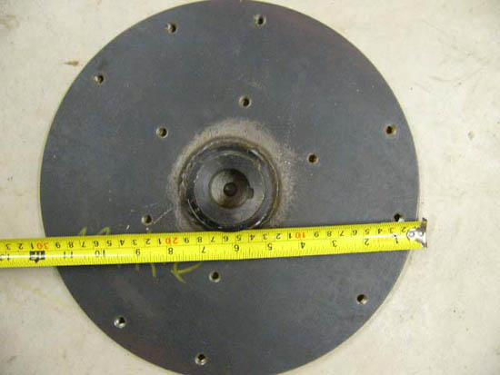
The centre hole is clearance for a 3/8-24 bolt to secure it to the genny shaft. I tapped a 3/8-24 thread in the shaft because I wanted more than just the keyway setscrews holding the hub and prop on. Each blade will be bolted to the hub with 5 5 /16-24 stainless bolts with lock washers just like Zubbly's hub!! I would like to supplement my household electric hot water heater some day, or work shop lighting depending on the output of the genny. The numbers leave a lot to be desired, maybe I can squeeze more out of it by reconfiguring the wiring. I use a Thermor Home Weather Station, winds vary: light 7 km/h, moderate 18km/h-25km/hr, to winds over 30km/h usually in the winter.I have not considered batteries yet as output will dictate my direction of prop size, battery bank size etc. It's been fun and I am learning alot!
Thanks for reading and I hope you enjoyed. As always, all comments and advice welcome.
Mike
