Author Topic: 3 Phase "Kicker"  (Read 3470 times)

0 Members and 1 Guest are viewing this topic.

jimovonz

  • Sr. Member
  • ****
  • Posts: 339
3 Phase "Kicker"
« on: March 15, 2006, 01:22:51 PM »
This is a circuit I put together when I first started playing with the F&P smartdrives. I promised to give it to brucedownunder some time ago but could only find an incomplete scribble and the original board was long since scavanged for parts. As I am once again playing with the smartdrives, I thought it might be fun to put another one together. The circuit is very simple and is based on a picaxe 08M. I used parts that I already had but you can probably get away with anything similar. If I were to buy the parts I used it would cost around $NZ30 ($US20) including the picaxe and protoboard.

The smartdrive motor suffers from cogging and typically won't start up until the wind hits around 30kph (18mph), however once going it will produce power down to around 10. In an attempt to improve the low wind performance I built this circuit to give the alt a kick start. It operates by pulsing each phase in turn in the appropriate sequence to drive the rotor - much the same as is done when the same motor is used in an F&P washing machine. When used in a washing machine, hall effect sensors are used to determine the exact time to pulse each phase. Unfortunately to use this method requires either placing the controller at the top of the pole and supplyng it power, or running a number of extra wires down (I have actually done this as well, but thats another more complicated project...) This circuit requires a star wired alt with the centre connection brought down the pole as well (total of four conductors - maybe possible to use the pole as a conductor???). The magnets on the rotor can be in any one of 6 positions relative to the coils (3 phases x 2 poles) and this solution is optimised for only one of them. However this shouldn't be a problem as the other 5 positions still result in a 'kick', though not nearly as hefty. If the turbine doesn't start after the first attempt, the odds are that the rotor is now stopped in a new position and you get another chance. Obviously there's a 1:6 chance of hitting the sweet spot in any attempt. The kick when applied in the correct rotor position will result in more than one full turn of the rotor (hopefully a lot more!!) The 'kick' is triggered by closing a normally open switch. At this stage I have not tried this circuit on a turbine in actual use. My intention was to use a 'gust gauge' mounted on the tower to activate it. One way to make a 'gust gauge' might be to suspend a ballcock lever (round plastic ball on the end of a brass rod used in troughs, cisterns etc) in the middle of a suitably sized electrically conductive ring. The ballcock arm is free to swing in the wind and can be adjusted by adding weight (maybe sand in the ball?) When the wind blows sufficiently enough to move the ball and make the lever touch the ring, the 'kicker' is activated. Suitable delays can be implemented using the picaxe to ensure the kicker only tries once in any one gust and  doesn't try to kick while the wind is already sufficient to turn the prop etc.


Here is a schematic showing the actual components I used:


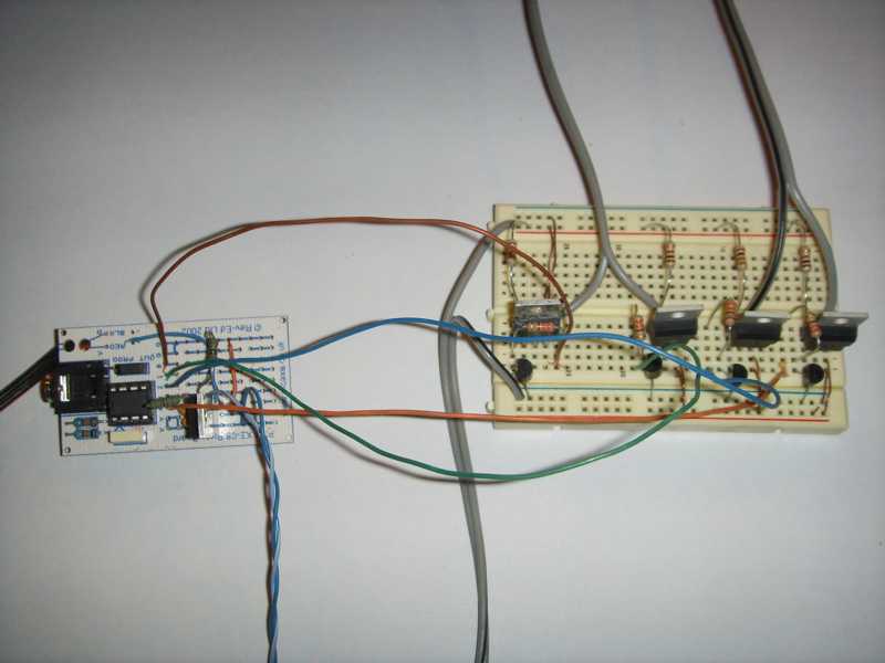
Here is a photo of the actual circuit:


Here is a video of the "kicker" in action (~1Mb):

http://www.otherpower.com/images/scimages/2210/FnPKick.AVI


Here is a scribble showing how the kicker is connected:


Here is the picaxe code I used in the video:

http://www.otherpower.com/images/scimages/2210/FnPKick.bas


The pulse durations and delays were derrived experimentally and are probably unique to each setup. I stopped when I achieved one complete rotation but there is nothing stopping you from going on finding pulse/pause lengths to get more 'kick'. The only limit is the program memory on the picaxe.

« Last Edit: March 15, 2006, 01:22:51 PM by (unknown) »

BruceDownunder

  • Full Member
  • ***
  • Posts: 159
  • Country: au
Re: 3 Phase "Kicker"
« Reply #1 on: March 15, 2006, 08:39:07 AM »
Thanks Jim .


 I remember you were playing around with this -I'll print this out and go have a play-My conclusions are that the "ART" 7 foot blades are a bit slender for these F&P ,possibly needing more chord width at the base -.

Thanks for the effort.

Bruce

« Last Edit: March 15, 2006, 08:39:07 AM by BruceDownunder »

jimovonz

  • Sr. Member
  • ****
  • Posts: 339
Re: 3 Phase "Kicker"
« Reply #2 on: March 15, 2006, 04:06:40 PM »
This system is very simple and includes none of the protection you would like for use in the real world. The fets I've used are rated at 60V but this could easily be surpassed if the battery was disconnected from the circuit when the turbine was producing power. Some form of reverse polarity protection would be a good idea too (as I just found out when I changed the battery and fried the picaxe!). I don't believe that any heat sinking is required as the fets get very little work. Even in repeated testing they never got warm

The picaxe depicted in the schematic is labeled '1kHz', this is of no consequence. I simply used another component (signal generator) to represent it in Circuitmaker. I also forgot to show the ground connection for the picaxe and left out the serial connection - which isn't strictly required as the chip can be programmed in another board. It is however already present on the prototype board which I highly recommend using if you are new to the picaxe (don't forget the jumper to enable programming/output port 0!). Nothing more than the prototype board ($NZ8), the picaxe 08M ($NZ6), the serial cable (make your own) and the free software are required to use the picaxe system as I have here.
« Last Edit: March 15, 2006, 04:06:40 PM by jimovonz »

willib

  • SuperHero Member
  • ******
  • Posts: 2414
  • Country: us
Re: 3 Phase "Kicker"
« Reply #3 on: March 15, 2006, 04:49:11 PM »
Jim i noticed that too..about the FETs not even getting hot!

although i did fry the connector to the battery ( a cheapo 12v cigarette lighter plug)

i guess it didnt like the 5A i was putting through it ..

even so the fet didnt get hot.

when i hooked the PWM up to a motor  with 24V ( two batteries) it did get hot at 2A ,but that was prolly because i had no diode in place to handle the inductor reverse emf of the motor..


one fried connector ..


« Last Edit: March 15, 2006, 04:49:11 PM by willib »
Carpe Ventum (Seize the Wind)

jimovonz

  • Sr. Member
  • ****
  • Posts: 339
Re: 3 Phase "Kicker"
« Reply #4 on: March 15, 2006, 05:02:43 PM »
Very low rdson values make high current easy, however as some have pointed out, high frequency switching can make things harder. Until I tried to implement a MPPT circuit I had no reason to go beyond a few kHz. Due to the size requirements of inductors at low frequency/high power I really needed to be up around 20+kHz. My usual gate drive circuits were not up to the task as they needed to supply/sink around 2A peak to minimise turn on/off times. I have got around that now by using both N and P channel fets to drive the gates of an array of fets in parallel. The gate drive fets are driven as I normally would.

How are you driving your fets? At what frequency?
« Last Edit: March 15, 2006, 05:02:43 PM by jimovonz »

willib

  • SuperHero Member
  • ******
  • Posts: 2414
  • Country: us
Re: 3 Phase "Kicker"
« Reply #5 on: March 15, 2006, 05:11:18 PM »
I'm driving it directly off of the PIC16F88 PWM output pin, at 1KHZ ..
« Last Edit: March 15, 2006, 05:11:18 PM by willib »
Carpe Ventum (Seize the Wind)

willib

  • SuperHero Member
  • ******
  • Posts: 2414
  • Country: us
Re: 3 Phase "Kicker"
« Reply #6 on: March 15, 2006, 05:41:07 PM »
This is the circuit.

http://www.otherpower.com/images/scimages/2965/pwm_circuit2.JPG 38KB

ps i tried to see your video ,it downloaded but wouldnt play, dont know what happened..
« Last Edit: March 15, 2006, 05:41:07 PM by willib »
Carpe Ventum (Seize the Wind)

jimovonz

  • Sr. Member
  • ****
  • Posts: 339
Re: 3 Phase "Kicker"
« Reply #7 on: March 15, 2006, 05:56:13 PM »
That'll cause you trouble at higher power levels I believe. I think the pic can only source around 25ma max on any one pin. You are obviously using a 'Logic FET' if you are only driving it with 5V. Even so called logic fets benefit from a bit more gate voltage. I usually try to supply at least 10V. Try something similar to what I've done above and I'm sure it will make a difference
« Last Edit: March 15, 2006, 05:56:13 PM by jimovonz »

jimovonz

  • Sr. Member
  • ****
  • Posts: 339
Re: 3 Phase "Kicker"
« Reply #8 on: March 15, 2006, 05:58:00 PM »
The movie comes straight off a Samsung digital camera. I'm not sure what codec it uses, but it was already on my system (XP). Anyone else have problems???
« Last Edit: March 15, 2006, 05:58:00 PM by jimovonz »

jimovonz

  • Sr. Member
  • ****
  • Posts: 339
Re: 3 Phase "Kicker"
« Reply #9 on: March 15, 2006, 06:48:10 PM »
I can't quite make out the fet spec. IRF?703???
« Last Edit: March 15, 2006, 06:48:10 PM by jimovonz »

domwild

  • Sr. Member
  • ****
  • Posts: 357
Re: 3 Phase "Kicker"
« Reply #10 on: March 15, 2006, 07:40:30 PM »
Jim,


Thanks for that. Commanda also published a kicker circuit once, which you would have seen. Am interested in using a Picaxe for "everything", like pulse charging with the PWM command, star/delta switching, load shedding, RPM sensing, etc.


Have given up the idea of a kicker to get a cogging F&P to turn as a larger prop will turn a recalcitrant F&P, albeit at lower RPM; see my diary entry. But one needs to experiment like you do to get somewhere.


When I was toying with using a tractor generator a gust detector came to mind which looks as follows:


A vertical square piece of tin on a hinge connected to a mercury float switch. It must be connected to the rudder so it faces square into the wind. Your setup is independent of wind direction, good idea. It does not have to be mounted on top of the mast.

*

« Last Edit: March 15, 2006, 07:40:30 PM by domwild »

jimovonz

  • Sr. Member
  • ****
  • Posts: 339
Re: 3 Phase "Kicker"
« Reply #11 on: March 15, 2006, 08:37:00 PM »
I'm a bit greedy, I would like max power across the board and I think the larger blades requiured to get a good low end, hurt the high end too much... I'll test a few blade sizes once (if...) I get my MPPT working.

If you ever need any help with the picaxe I'm only too happy to lend a hand. I'll send you an email so you can contact me direct if you wish - though its probably a good idea to post on the board so others can benefit. I really feel that for beginners, you can't go past the picaxe (perfectly suitable for a number of more advanced projects as well!)
« Last Edit: March 15, 2006, 08:37:00 PM by jimovonz »

willib

  • SuperHero Member
  • ******
  • Posts: 2414
  • Country: us
Re: 3 Phase "Kicker"
« Reply #12 on: March 15, 2006, 09:54:53 PM »
it's an IRF 3703 , nice FET..
« Last Edit: March 15, 2006, 09:54:53 PM by willib »
Carpe Ventum (Seize the Wind)

jimovonz

  • Sr. Member
  • ****
  • Posts: 339
Re: 3 Phase "Kicker"
« Reply #13 on: March 15, 2006, 10:07:22 PM »
From the spec sheet, you must be only just turning this fet on with 5V, 25ma source @ 1kHz! I'm sure that any heating your encountering will go away if you drive it better. Put the gate on voltage on the scope while you are driving it and you should see something far different from the 5V square wave that you may think your driving it with. Obviously for small loads driven at low frequency this won't matter.
« Last Edit: March 15, 2006, 10:07:22 PM by jimovonz »

willib

  • SuperHero Member
  • ******
  • Posts: 2414
  • Country: us
Re: 3 Phase "Kicker"
« Reply #14 on: March 15, 2006, 10:12:03 PM »
that is the gate voltage on the scope


 link to my diary..

http://www.fieldlines.com/comments/2006/3/12/5250/58585/5#5

« Last Edit: March 15, 2006, 10:12:03 PM by willib »
Carpe Ventum (Seize the Wind)

jimovonz

  • Sr. Member
  • ****
  • Posts: 339
Re: 3 Phase "Kicker"
« Reply #15 on: March 15, 2006, 11:34:38 PM »
Is it driving the gate with the fet under load? Can you confirm that you are driving the gate with 5v? Anything is possible, but I would expect to see the gate voltage ramp up/down as the gate charges/discharges. I have never had much luck direct driving a fet - even the so called logic level fets. You mention that the scope is on  0.5ms/division. I count at least 7 divisions in a cycle, but it could be more as it doesn't show one complete cycle. 7 divisions = 285Hz, more divisions is slower. It is possible that this is not fast enough to show the effect I'm describing.
« Last Edit: March 15, 2006, 11:34:38 PM by jimovonz »

willib

  • SuperHero Member
  • ******
  • Posts: 2414
  • Country: us
Re: 3 Phase "Kicker"
« Reply #16 on: March 16, 2006, 12:20:15 AM »
"Is it driving the gate with the fet under load?"

Yes up to 5A , i didnt want to push it further .

its 6.6 divisions for one complete cycle , 1/(6.6* .0005) =303 hz


" It is possible that this is not fast enough to show the effect I'm describing."

Yes that's possible ... , 303 Hz is not really that fast...


for some reason i had 1Khz in mind but it was really 303Hz , sorry bout that..

« Last Edit: March 16, 2006, 12:20:15 AM by willib »
Carpe Ventum (Seize the Wind)

jimovonz

  • Sr. Member
  • ****
  • Posts: 339
Re: 3 Phase "Kicker"
« Reply #17 on: March 16, 2006, 01:08:27 AM »
For a lot of things that speed is fine, so do what ever works!
« Last Edit: March 16, 2006, 01:08:27 AM by jimovonz »