So let me get this straight...
1. DanB has supplied you with one of his beautiful machines cut in 7mph, 12v
2. By 15mph, it would be doing 500W or so, and being greedy you wish to extract more power out at higher speeds at 24v and still get the benefit between 7 and 15 mph?
I'm happy with that, in this case greed is power.
Well looks like a doubler in the 500w range is what your after.
Ok, had another fiddle with it last night and decided the wave form under load was "shabby" and was the cause of my inefficiency. Rebuilt the current sensing system from the down and dirty to the not quite so dirty.
The improvement was quite startling. Because of the totally unacceptable layout (long current carrying wires ratsnested all over the bench), the original current limiter was high gain by definition. This meant that it was susceptable to poor layout in a big way, and the more power going through it, the more the waveform suffered from interference from it. This led to the inefficiecies.. I thought i'd be smart and just add more fets and diodes (your suggestion I think), it worked, but it only hid the underlying poor design and layout. Temp was down, efficiency was also.
So having decided to do something about it before I scrapped this experiment, I had to solve this "noise"..... just because...
I used a tiny current sense coil 1 turn: 200 turns (spiderweb thick 200 turns) on a very small ferrite.. The whole coil 1/2"cubed. This gave my over the top control voltages..(over 50v peak), so we have gone overboard again. This was rectified and fed into the op amp, and suddenly the waveform was stable over a very large range (0-30A) No degradation occured at all. Completly stable even with my rats nest.
The interesting thing from this is that with just two mosfets with no heat sink at all, at 50w it stayed stone motherless cold. I couldn't calculate the efficiency to within 5-10% of what was true, as the amp meters were so coarse in their scale that the figures from sight reading came out at 100% which is nonsense, but there was no denying that there was no heat discernable at all in the fets. The new waveform must be close to perfect.
At 120w the two fets only got to luke warm, and once again the efficiency readings were useless as they were so close to unity that with these meters I could not measure what really was going on. But with less then 1 sq cm of cooling on the fets, they stayed very cool.
Up at 30A, there was no appreciable temp rise (only for short periods, as the battery being charged was suffering badly V=18.6 after only 10 seconds.
If you want I will go further with this and try it on the big batteries in the Grader, then I should be able to check the watts without them changing radically at higher powers.
If this goes as planned I will post the circuit etc. Should get away with building it for peanuts.
Is this the kind of thing your after.
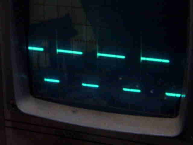
For the grand finale, I will try and post a pic of the scope output at 300W (approx)
It looks like more power is simply more fets and diodes. The design seems very stable regardless of my crummy build
..............oztules
