Author Topic: The Chassis  (Read 1276 times)

0 Members and 1 Guest are viewing this topic.

Murlin

  • Full Member
  • ***
  • Posts: 221
The Chassis
« on: June 26, 2006, 01:43:32 AM »
Here are some chassis pics, If I have made any mistakes please tell me :)


« Last Edit: June 26, 2006, 01:43:32 AM by (unknown) »

SamoaPower

  • Sr. Member
  • ****
  • Posts: 417
Re: The Chassis
« Reply #1 on: June 26, 2006, 05:27:30 PM »
WOW, sure is hell for stout!


I'm wondering about your reasoning for choosing a separate brake when you have a pretty good one built into the alternator. By shorting the output lines, perhaps progressively, I think you'll find it comes to a halt pretty well at moderate speeds. It depends somewhat on your matching between the air rotor and the alternator and the load. If your rotor can significantly overpower the alternator it won't replace some form of furling but once slowed down by furling, it could lock up rotor. Matched systems are best.

« Last Edit: June 26, 2006, 05:27:30 PM by SamoaPower »

Murlin

  • Full Member
  • ***
  • Posts: 221
Re: The Chassis
« Reply #2 on: June 27, 2006, 05:56:39 AM »
"I'm wondering about your reasoning for choosing a separate brake when you have a pretty good one built into the alternator."


It's just a redundant backup brake should I loose the stator.  I know it is way overkill, but you never know about things.


I think such a brake could actually stop it if there was a runaway.


Even with it furled I think that the 20' blades would still want to run at Mach 2 if you lost the stator due to a problem, no reason to just sit back and let it the blades blow up on you...saving a set of blades pays for the added cost of the brake.


It adds about another 80 lbs.  But the tower will take handle it.


I want it nice and rigid so the yawing stresses will not affect it as much.


It also gets the blades a little further from the pole.


It's probably a stupid idea, but since all this stuff is experimental.....let's experiment.....


Murlin

« Last Edit: June 27, 2006, 05:56:39 AM by Murlin »

SamoaPower

  • Sr. Member
  • ****
  • Posts: 417
Re: The Chassis
« Reply #3 on: June 27, 2006, 05:50:24 PM »
No, I don't think it's stupid but 80lb and cost is a fair penalty to pay.


"I think such a brake could actually stop it if there was a runaway."

So could variable pitch which has other additional benefits.


"I want it nice and rigid so the yawing stresses will not affect it as much."

Yaw control can eliminate those stresses.


"It also gets the blades a little further from the pole."

Another nice advantage to a downwind configuration.


Keep thinking on it Murlin, you're getting there.

« Last Edit: June 27, 2006, 05:50:24 PM by SamoaPower »

oztules

  • Hero Member
  • *****
  • Posts: 1477
  • Country: aq
  • Village idiot
Re: The Chassis
« Reply #4 on: June 27, 2006, 06:22:04 PM »
Hi Merlin,

Where do you intend to place the rotors?


I think that if you are going to build a custom brake drum, then perhaps you can use it for the rotor carrier as well, and machine in mating surfaces for the rotors on this


This design would then allow you to machine the rotor plate's inners out to the drum brake outer diameter, saving 8- 10 inches of thick rotor steel (depending on the size of the brake drum) this may mitigate the weight impost of the braking system.


It should also provide for a stiffer rotor gap as the drum brake will provide a solid flange to bolt the rotors to, and be a much larger diameter than the hub, and so allow for finer tolerances in gap width.


just a thought..............oztules

« Last Edit: June 27, 2006, 06:22:04 PM by oztules »
Flinders Island Australia

Murlin

  • Full Member
  • ***
  • Posts: 221
Re: The Chassis
« Reply #5 on: June 28, 2006, 12:48:04 PM »
This pic should help


The alternator mounts in the traditional place on the green hub.  It is an off the shelf Item I got over the internet from the trailer superstore.  3500 lbs.  The bolt pattern is 8 X 6 1/2 and so the total bearing for the alternator to sit on is about 8 inches.


If the prop nut is cleared by 1/2" or so, hopefully any violent yawing stresses will not flex the rotors and make them rub on the stator at all...


The brake assembly added 5 inches to the total length from the prop nut to the yaw axis over the current designs.


I hope that doesn't change the yawing characteristics so much that I can't fix it with changes to the tail feathers..


Murlin

« Last Edit: June 28, 2006, 12:48:04 PM by Murlin »

Murlin

  • Full Member
  • ***
  • Posts: 221
Re: The Chassis
« Reply #6 on: June 29, 2006, 01:25:14 PM »
Sorry OZ I forgot to mention that the break drum is a piece of 1/2" thick flat plate with teeth cut on the inside of it to match the hub.


I am hoping to get my hands on a piece of schd 40 12" pipe to weld on the plate for the drum.


If I have it figures correctly, the brake is 12.250 diameter and the schd 40 inside dia would be 12" with a 3/8" wall.  


When its all welded together, turning the ID out to 12.25 and end up with a 1/4" wall thickness should be ok for just a emergency/parking brake.

« Last Edit: June 29, 2006, 01:25:14 PM by Murlin »

oztules

  • Hero Member
  • *****
  • Posts: 1477
  • Country: aq
  • Village idiot
Re: The Chassis
« Reply #7 on: June 29, 2006, 06:56:32 PM »
Sorry Merlin, I was thinking of something like this.


I'm no good with the drawing aspect, so here we go.

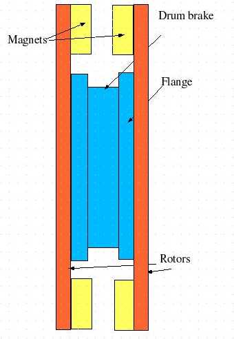
Perhaps use the drum as the rotor carrier, this gets rid of the first 12" of rotor disk steel x2...in your case 12"x 1/2" x2 of solid steel not needed to carry


The flanges can be rings welded on to the drum and machined to a true surface to face and bolt the rotors against.


The front of the drum (1/2" steel) would support the bearing carrier (welded to it using heavy pipe of whatever diam suits your bearings and machined out.)


This is simple, strong, and allows the brake drum to perform all the hub functions as well as be a drum brake.


This requires some decent machining, but this odes not appear to be a problem for you. You have to be able to deal with the 12" pipe/brake drum fabrication anyway, this just add a few more steps.... and much stronger and no rotor warp is going to happen here, so can use thinner (5/16) steel for the rotors. ( assume you were shooting for 3/8 or heavier for these if only stud mounted)


what do you think?


.............oztules

« Last Edit: June 29, 2006, 06:56:32 PM by oztules »
Flinders Island Australia

oztules

  • Hero Member
  • *****
  • Posts: 1477
  • Country: aq
  • Village idiot
Re: The Chassis
« Reply #8 on: June 29, 2006, 07:03:22 PM »
Sorry Merlin, my post doesn't make it clear that I mean make your own bearing hub as an intefral part of the drum brake.. ie heavy walled tubing welded to the inside front of the drum, and machined out to take the bearing shells. This will allow you to extend the bearing to bearing length to a longer length, and so get rid of some of the possible bearing slop that short hub bearings can give.


..........oztules

« Last Edit: June 29, 2006, 07:03:22 PM by oztules »
Flinders Island Australia

Murlin

  • Full Member
  • ***
  • Posts: 221
Re: The Chassis
« Reply #9 on: June 30, 2006, 06:57:45 AM »
Interesting design....I will do some modeling on that concept...it would make for a shorter distance from the nut to the yaw axis....


Murlin

« Last Edit: June 30, 2006, 06:57:45 AM by Murlin »