Author Topic: NACA 4415  (Read 35640 times)

0 Members and 1 Guest are viewing this topic.

willib

  • SuperHero Member
  • ******
  • Posts: 2414
  • Country: us
Re: NACA 4415
« Reply #33 on: July 26, 2006, 08:28:37 PM »
Damnit i wish i had'nt said that

i was in sort of a bad mood

sorry
« Last Edit: July 26, 2006, 08:28:37 PM by willib »
Carpe Ventum (Seize the Wind)

finnsawyer

  • Hero Member
  • *****
  • Posts: 1565
Re: NACA 4415
« Reply #34 on: July 27, 2006, 08:43:06 AM »
What's the point of being a doer if you don't know what your are doing?  You can follow what most people are doing here.  But by posting this you implied you have entered the realm of the thinker, which opens up all kinds of issues.  What escapes me is why you didn't check the existing data for the 4415 profile, as it surely exists being a NACA air foil profile.  I am sure you would have found a much different curve for the drag coefficient.  I would like to call your attention to graph B32.  Note the lower curve that has a pressure coefficient as large as one.  I take that to be pressure above that of the incident wind.  As such, it results in a force against the leading edge of the wing.  That is, it results in drag. Unfortunately you need this build up of pressure along the leading edge to give the speed up in air flow along the top surface that results in lower pressure there and lift.  So, this component of drag and the lift are intricately related.  


If you are willing to pay me $100,000.00 a year, I will drop everything I am doing and will advise you (develop the necessary equations or computer programs) in doing whatever it is you are trying to do.  As it is, you are getting these insights for free.  It's up to you to put them to good use.  

« Last Edit: July 27, 2006, 08:43:06 AM by finnsawyer »

willib

  • SuperHero Member
  • ******
  • Posts: 2414
  • Country: us
Re: NACA 4415
« Reply #35 on: July 27, 2006, 10:03:48 AM »
"What escapes me is why you didn't check the existing data for the 4415 profile, as it surely exists being a NACA air foil profile"


 the online data for the airfoil (the SG6050) that i am using is somewhat lacking  , BUT it is real close to the NACA4415 ,which there is lots of data for , i believe i stated that earlier in this thread .

its not exact , but its close enough for me :)

the differences i can see are the sg6050 has a slightly pointier nose , it is a tad thicker , and lacks the slight camber twards the trailing edge , but like i said close enough for government work.

i agree the pressure, on the lower part of the graph ,is the pressure above the foil , from the incident wind side of the foil, even though they call it a coeficient it is really sort of a direct pressure reading from pressure sensors located on the upper and lower part of the airfoil ,i'll try and find the part in the pdf where they talk about  the pressure sensors and how the data is presented.


« Last Edit: July 27, 2006, 10:03:48 AM by willib »
Carpe Ventum (Seize the Wind)

SamoaPower

  • Sr. Member
  • ****
  • Posts: 417
Re: NACA 4415
« Reply #36 on: July 27, 2006, 07:07:57 PM »
Now, what's this about doers and talkers?


« Last Edit: July 27, 2006, 07:07:57 PM by SamoaPower »

willib

  • SuperHero Member
  • ******
  • Posts: 2414
  • Country: us
Re: NACA 4415
« Reply #37 on: July 27, 2006, 07:30:41 PM »
Finally we get to see something from you, what took you so long?

i did apologize ...

what is that cool looking gaget third one down on the left ?

is that a wartman fx 60 airfoil top right? looks like it has depth to it?

cool planes too

is that a pitch control mechanism right above that cool looking gaget?
« Last Edit: July 27, 2006, 07:30:41 PM by willib »
Carpe Ventum (Seize the Wind)

willib

  • SuperHero Member
  • ******
  • Posts: 2414
  • Country: us
Re: NACA 4415
« Reply #38 on: July 27, 2006, 11:15:15 PM »
Test Equipment and Procedures

Data Acquisition

Data were acquired and processed from up to 60 surface pressure taps, three individual tunnel pressure transducers, and an angle of attack potentiometer. The data acquisition system included an IBM PC compatible 80386 based computer connected to a Pressure Systems Incorporated (PSI) data scanning system.

The PSI system included a 780B Data Acquisition and Control Unit (DACU), 780B Pressure Calibration Unit (PCU), 81-IFC scanning module interface, two ESP-32 5-psid range pressure scanning modules (ESPs), and a 30-channel Remotely Addressed Millivolt Module (RAMM-30).


Three individual pressure transducers read tunnel total pressure, tunnel east static pressure, and tunnel west static pressure. Before the test began, these transducers were bench calibrated using a water manometer to determine their sensitivities and offsets. Related values were entered into the data acquisition and reduction program so the transducers could be shunt resistor calibrated before each series of wind tunnel runs.

The angle of attack potentiometer was a linear rotary potentiometer and was regularly calibrated during the tunnel pressure transducers shunt calibration. The angle of attack calibration was accomplished by taking voltage readings at known values of set angle of attack. This calibration method gave angle of attack

readings within ±0.25° of actual over the entire angle range.

Two ESPs were calibrated simultaneously using the DACU and PCU. At the operator's request, the DACU commanded the PCU to apply known regulated pressures to the ESPs and read the output voltages from each integrated pressure sensor. From these values, the DACU calculated the calibration coefficients and stored them internally until the coefficients were requested by the controlling computer. This calibration was done several times during a run set because the ESPs were installed inside the model and their outputs tended to drift with temperature changes during a test sequence. Frequent online calibrations minimized the effect.

Finally, at the operator's request, pressure measurements from the airfoil surface taps and all other channels of information were acquired and stored by the DACU and subsequently passed to the controlling computer for final processing.


Data Reduction

The data reduction routine was incorporated as a section of the data acquisition program. This combination of data acquisition and reduction routines allowed data to be reduced online during a test. By quickly reducing selected runs, integrity checks could be made to ensure the equipment was working properly and to enable timely decisions about the test matrix.

The ambient pressure and tunnel air temperature were manually input into the computer and were updated regularly. These values, as well as the measurements from the tunnel pressure transducers, were used to calculate tunnel airspeed. As a continuous check of readings, both the tunnel individual pressure transducers

and the ESPs, read the tunnel total and static pressures.

A typical datum point was derived by acquiring twenty data scans of all channels over a 1-second window at each angle of attack and tunnel condition. The reduction portion of the program processed each data scan to coefficient forms Cp, Cl, Cm¼, and Cdp using the measured surface pressure voltages, calibration coefficients, tap locations and wind tunnel conditions. All scan sets for a given condition were then ensemble averaged to provide one set. All data were saved in electronic form. The data were not corrected for any tunnel wall effects, etc.

Test Matrix

The test was designed to allow an extended angle of attack range of -60° to 230° and Reynolds numbers of 1, 1.5, and 2 million with and without LEGR. Tabular data in Appendix B contains the actual Reynolds number for each angle of attack. The angle of attack increment was four degrees when <-20° or >40°, two degrees when -20°<  <10° or 20°<  <40°, and one degree when 10°<  <20°. All test speeds and angles of attack were set for model clean and LEGR conditions.
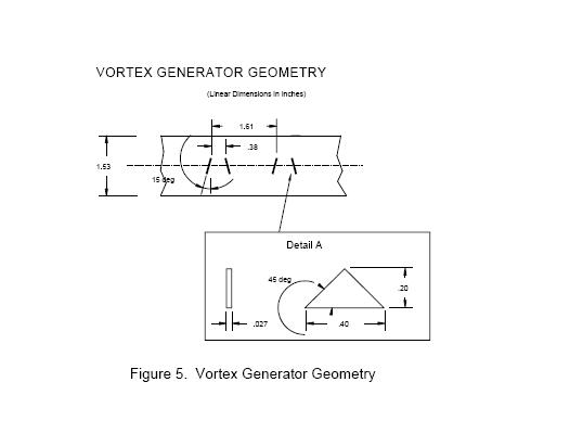


For some cases, VGs were mounted at the 30% chord position on the model's upper surface only. The VG strips were provided by U.S. Windpower and were the exact type used on wind turbines in the field. Test conditions while the VGs were applied included clean and LEGR data at 1 and 1.5 million Reynolds numbers

over an angle of attack range of -20° to 40°.


Summary

A NACA 4415 model was installed in the OSU/AARL 7x10 subsonic wind tunnel and tested at three Reynolds numbers and with model clean, roughened, and with VGs. Table 1 is a summary of the aerodynamic coefficient data for the NACA 4415.
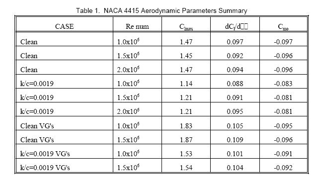


For the clean NACA 4415 model, Reynolds number changes from 1 to 2 million did not have a significant effect on the maximum positive lift or the pitching moment at zero degrees angle of attack. However, the addition of leading edge grit roughness to the model reduced the maximum lift coefficient by 18% and caused a 16% change in the pitching moment at 0° angle of attack. Also, the lift curve slope showed

increases with Reynolds number. Adding VGS on the model upper surface at the 30% chord station caused the maximum lift coefficient to increase by 29% in the clean cases and about 27% for the roughened cases.

The VGs apparently energized the boundary layer sufficiently to increase the lift curve slope and to delay stall to a higher angle of attack resulting in a higher maximum lift coefficient. However, the positive stall with VGs was more abrupt than the stall without VGs.

« Last Edit: July 27, 2006, 11:15:15 PM by willib »
Carpe Ventum (Seize the Wind)

finnsawyer

  • Hero Member
  • *****
  • Posts: 1565
Re: NACA 4415
« Reply #39 on: July 28, 2006, 08:06:22 AM »
I don't have time to try and digest this now.  I'd simply like to say that I haven't seen anything really revolutionary concerning air foils.  As far I can tell they all behave (have lift and drag coefficient behavior) about the same.  As such, from the standpoint of the home experimenter it doesn't make much difference what profile they use, including simply having a flat back surface.  You might check it out.  From my perspective there are other more interesting issues to consider that may yield better results than fiddling with air foil shapes.  You also ought to keep in mind that a 50 per cent increase in output only requires about a 15 per cent increase in wind speed.  How many people can make the necessary measurements to the accuracy required in the field (not in a wind tunnel)?  Ever wonder why the leading edge of an air plane wing is rounded rather than a knife edge, which would have less drag?  
« Last Edit: July 28, 2006, 08:06:22 AM by finnsawyer »

willib

  • SuperHero Member
  • ******
  • Posts: 2414
  • Country: us
Re: NACA 4415
« Reply #40 on: July 28, 2006, 09:16:58 AM »
"Ever wonder why the leading edge of an air plane wing is rounded rather than a knife edge, which would have less drag?"


i'm not sure how one would incorporate a wing with a knife edge into an airfoil shape

i can tell you that proportionally  enlarging  the airfoil that i have to a 21" chord , brings the leading edge up to a 1/2" radius..

sort of blunt ,but that part of the blade isnt going as fast as the tip is.


i found it interresting in the last paragraph about the Vortex Generators (VGs).


"Adding VGs on the model upper surface at the 30% chord station caused

the maximum lift coefficient to increase by 29% in the clean cases and about 27% for the roughened cases.

The VGs apparently energized the boundary layer sufficiently to increase the lift curve slope and to delay

stall to a higher angle of attack resulting in a higher maximum lift coefficient. However, the positive stall with VGs was more abrupt than the stall without VGs."


.

« Last Edit: July 28, 2006, 09:16:58 AM by willib »
Carpe Ventum (Seize the Wind)

willib

  • SuperHero Member
  • ******
  • Posts: 2414
  • Country: us
Re: NACA 4415
« Reply #41 on: July 28, 2006, 01:42:19 PM »
"As such, from the standpoint of the home experimenter it doesn't make much difference what profile they use, including simply having a flat back surface."


all i meant was the NACA 4415 was close enough to the SG5060 that it seemed to me that i could use the 4415 results and apply them to the SG6050 .

« Last Edit: July 28, 2006, 01:42:19 PM by willib »
Carpe Ventum (Seize the Wind)

finnsawyer

  • Hero Member
  • *****
  • Posts: 1565
Re: NACA 4415
« Reply #42 on: July 29, 2006, 09:20:43 AM »
The 15 in the 4415 means that the thickness of the air foil is 15 per cent of the length.  There are also tables for 12 per cent thicknesses.  Air plane design involves compromises between many competing requirements.  One is the need for a spar of sufficient strength in the wing.  Does this determine the shape of the wing with the blunt edge or are there other considerations?  One could (conceptually) continue the shape of the air foil toward the wind to a knife edge, making it symmetrical and about doubling its length.  In the case of a wind mill blade the entire blade is the spar, so we don't need as much thickness.  There are those who advocate very thin blades, so maybe we should use a thin blade with a knife edge.  In my mind this leaves the question of what speeds up the air to cause the lower pressure along the top surface.  Since it requires a force to change the direction and speed of any mass, I think we need those blunt noses with the build up of pressure to get maximum lift.  Again we come back to the relationship between the drag caused by this pressure and the lift.


The use of the vortex generators may increase lift, but what will the effect on overall drag be?  If drag increased this could actually decrease performance.  Keep in mind that you can increase power with an air plane, but have no such option with a wind mill.  As you are aware, I am skeptical about their drag coefficient data.  I don't think it tells the whole story.  

« Last Edit: July 29, 2006, 09:20:43 AM by finnsawyer »

willib

  • SuperHero Member
  • ******
  • Posts: 2414
  • Country: us
Re: NACA 4415
« Reply #43 on: July 29, 2006, 09:51:29 AM »
http://www.desktopaero.com/appliedaero/airfoils1/airfoilgeometry.html


if you have java activated on your machine the above page is pretty cool ,as it lets you change the numbers of the  NACA airfoils and draws them for you..

« Last Edit: July 29, 2006, 09:51:29 AM by willib »
Carpe Ventum (Seize the Wind)

Murlin

  • Full Member
  • ***
  • Posts: 221
Re: ...by no means least
« Reply #44 on: August 01, 2006, 11:53:29 AM »
Sorry it took so long to get back, been on vacation and will be putting out fires all month.


The balsa skin was 1/16" thick and the wing was around 8', with about a 10" chord width.


The airfoil did look close to the 4415..


Murlin

« Last Edit: August 01, 2006, 11:53:29 AM by Murlin »

willib

  • SuperHero Member
  • ******
  • Posts: 2414
  • Country: us
my latest creations
« Reply #45 on: August 01, 2006, 07:29:18 PM »
i started them late sturday night, i worked on and off on them sunday ,and finished them yesterday, i still have to hit them with fine sandpaper

as you can see they are real small , but still the alt doesnt stop when shorted , although it does spin very slowly.

they spin at 263 RPM , with the fan on high no load.


maybe tomorrow evening i can get out an give them a spin with real wind
« Last Edit: August 01, 2006, 07:29:18 PM by willib »
Carpe Ventum (Seize the Wind)