Author Topic: magnetic flux (gauss) meter  (Read 11312 times)

0 Members and 1 Guest are viewing this topic.

willib

  • SuperHero Member
  • ******
  • Posts: 2414
  • Country: us
magnetic flux (gauss) meter
« on: August 13, 2006, 05:57:37 AM »
I thought i would do a little investigating today .

Hall sensors as i found out can be found in old CD rom drive motors


here is three that i got out of one motor

on the right  is my trusty Weller with the attachment that i used to get them off

http://www.rcgroups.com/forums/showthread.php?t=307133


the above site has all the info on how to make a gauss meter

i want to  use it to measure current for my data logger


Hall switches are slightly different , in that they switch from plus to minus as the magnetic field of a rotating alternator switches.


i've allready used a hall switch to measure RPMs on my test bed , hall switches can be found in pc powersupply fans.


so the hall switches can be used measure turbine RPM as well as wind speed , by using the same fan with the armature removed , and keeping the fan part (with the magnets) and the circuit board intact


the goal is to assemble all the sensors needed to record data from a windmill


the hall sensor will output a voltage proportional to the current, thats the plan anyway.

it only took about five mins to get the motor out of a CD drive, the rotor with mags just pulls off , the tool i used to get them off ,is some 17 ga wire wrapped around a soldering iron


some other links i came across

http://my.execpc.com/~rhoadley/magmeter.htm

and a Dutch version

http://www.modelbouwforum.nl/phpBB2/viewtopic.php?t=7834

« Last Edit: August 13, 2006, 05:57:37 AM by (unknown) »
Carpe Ventum (Seize the Wind)

steeolico

  • Jr. Member
  • **
  • Posts: 75
Re: magnetic flux (gauss) meter
« Reply #1 on: August 13, 2006, 01:06:21 AM »
Molto interessante Willib!

A lot interesting Willib!

« Last Edit: August 13, 2006, 01:06:21 AM by steeolico »

jimovonz

  • Sr. Member
  • ****
  • Posts: 339
Re: magnetic flux (gauss) meter
« Reply #2 on: August 13, 2006, 01:45:15 AM »
« Last Edit: August 13, 2006, 01:45:15 AM by jimovonz »

willib

  • SuperHero Member
  • ******
  • Posts: 2414
  • Country: us
Re: magnetic flux (gauss) meter
« Reply #3 on: August 13, 2006, 09:42:34 AM »
Thanks i'm just trying to build on Warske's work

as Jim pointed out it can be found at


http://www.rcgroups.com/forums/showthread.php?t=307133


if anyone has a free hour , its worth a read , the discussion is captivating and the links are awesome !


it took about five mins to get this far

.

« Last Edit: August 13, 2006, 09:42:34 AM by willib »
Carpe Ventum (Seize the Wind)

willib

  • SuperHero Member
  • ******
  • Posts: 2414
  • Country: us
Re: magnetic flux (gauss) meter
« Reply #4 on: August 13, 2006, 09:51:41 AM »
Is that where you got your sensors from?

a cd drive ?


thats  them at six , four thirty , and three o'clock.

Warske peeled the metal off the back of the circuit board , but i saw no need to because the chips were allready visible , and accessable.

« Last Edit: August 13, 2006, 09:51:41 AM by willib »
Carpe Ventum (Seize the Wind)

willib

  • SuperHero Member
  • ******
  • Posts: 2414
  • Country: us
Preperations and soldering
« Reply #5 on: August 13, 2006, 11:57:05 AM »
i've tinned the wires in preparation for soldering

and put the chip in a clamp to hold it and soak up some heat just in case


all the wires went on smoothly


one came off so i had to redo it


all wires are on


time for fun

« Last Edit: August 13, 2006, 11:57:05 AM by willib »
Carpe Ventum (Seize the Wind)

willib

  • SuperHero Member
  • ******
  • Posts: 2414
  • Country: us
hall sensor pinout and schematic
« Reply #6 on: August 13, 2006, 12:09:54 PM »
following warske this is the pin out and a schematic


« Last Edit: August 13, 2006, 12:09:54 PM by willib »
Carpe Ventum (Seize the Wind)

willib

  • SuperHero Member
  • ******
  • Posts: 2414
  • Country: us
scope output
« Reply #7 on: August 13, 2006, 01:42:13 PM »
i was hopeing this would be the case


you could also use the sensor to measure RPM if necessary


sorry for the blurry pic but its hard to snap a shot when your turning the testbed.


with a 1.2V NiMH battery hooked up to the sensor , the scope is set at .5V per div


the reading from the sensor is about .6v peak ,  with the sensor in the path of the magnets

« Last Edit: August 13, 2006, 01:42:13 PM by willib »
Carpe Ventum (Seize the Wind)

stephent

  • Sr. Member
  • ****
  • Posts: 268
Re: magnetic flux (gauss) meter
« Reply #8 on: August 13, 2006, 01:52:14 PM »
Might be able to use one as a currant sensing device too.

Just watch which end is pointing to the mag or circuit.

The Hall's from the CD are nice and your project has started me thinking about Nando's controller using one as a currant sensing device for diversion purposes, maybe.

Thanks for the ideas....
« Last Edit: August 13, 2006, 01:52:14 PM by stephent »

dinges

  • Hero Member
  • *****
  • Posts: 1294
  • Country: nl
Re: magnetic flux (gauss) meter
« Reply #9 on: August 13, 2006, 03:46:33 PM »
I'd save that stator-thingy & rotor too. If the RC guys can convert it to motors, that same conversion should work as an alternator too. A mini windgenerator perhaps?


Ghurd, you read this?

« Last Edit: August 13, 2006, 03:46:33 PM by dinges »
“Research is what I'm doing when I don't know what I'm doing.” (W. von Braun)

ghurd

  • Super Hero Member Plus
  • *******
  • Posts: 8059
Re: magnetic flux (gauss) meter
« Reply #10 on: August 13, 2006, 06:08:12 PM »
Very low volts.  Half will not light an LED.

Sometimes a motor is better left as a motor.

G-
« Last Edit: August 13, 2006, 06:08:12 PM by ghurd »
www.ghurd.info<<<-----Information on my Controller

willib

  • SuperHero Member
  • ******
  • Posts: 2414
  • Country: us
current & RPM at the same time
« Reply #11 on: August 13, 2006, 07:43:35 PM »
Thanks for your comments

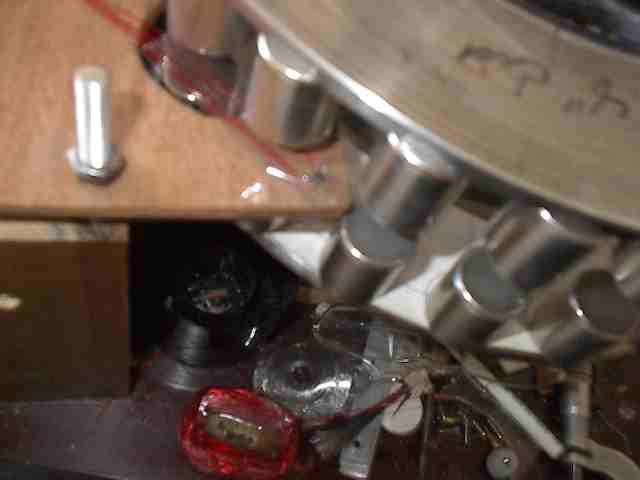
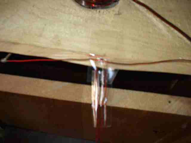
Below is the sensor between the magnets


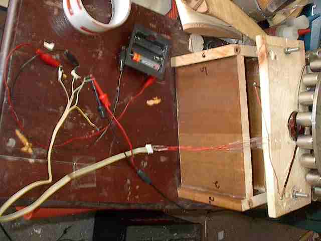
this is the setup , thats it on the right at the end of the wires, its powered by a single NiMH AA battery


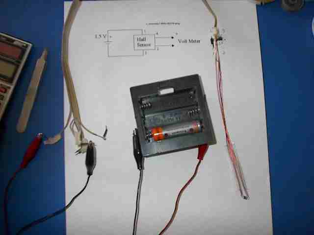
i  was just trying to get a reading off the coil here , i quess i need more turns


a close up of the sensor, i sure wish i could get better closeups , maybe if i use a magnifying glass they would come out better


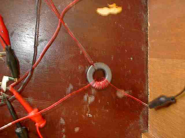
below is the setup that really worked well , its similar , if not exactly what Jim did , except that i've put it in the line comming from the test coil ,i have twelve or so turns wrapped around a ferrite toroid , with a slot cut in it and the sensor inserted in the opening


 and got great results , at low RPM the wave looks like a sine wave with a peak of .2V , at higher RPM i've had  .4V peak out of it , so the wave grows with an increase in current , and one could also measure RPM because its a sine wave


« Last Edit: August 13, 2006, 07:43:35 PM by willib »
Carpe Ventum (Seize the Wind)

willib

  • SuperHero Member
  • ******
  • Posts: 2414
  • Country: us
Re: magnetic flux (gauss) meter
« Reply #12 on: August 13, 2006, 09:24:07 PM »
yes but if you could spin it fast enough it would put out more power, also those RC people do a really , really cool job of putting small neos in place of the ceramic ones that come in the stock motor.

for the stator that i have , nine coils ,they would put 12 tiny neos , and make a nice three phase motor , their efficiency is up there too , because they also rewind their stators , and they put some amps into those little motors and crank them up to around  10000 RPM , they use them for helicopters and planes and are allways talking torque and efficency .
« Last Edit: August 13, 2006, 09:24:07 PM by willib »
Carpe Ventum (Seize the Wind)

ghurd

  • Super Hero Member Plus
  • *******
  • Posts: 8059
Re: magnetic flux (gauss) meter
« Reply #13 on: August 13, 2006, 09:57:11 PM »
I'm on the hunt for one of those DLT tape drives.

G-
« Last Edit: August 13, 2006, 09:57:11 PM by ghurd »
www.ghurd.info<<<-----Information on my Controller

kitno455

  • Sr. Member
  • ****
  • Posts: 442
Re: current & RPM at the same time
« Reply #14 on: August 14, 2006, 10:22:31 AM »
cool willi- see if your camera has a 'macro' mode- the icon often looks like a tulip or a mountain. set to 'tulip' mode, you might get better closeups


allan

« Last Edit: August 14, 2006, 10:22:31 AM by kitno455 »

willib

  • SuperHero Member
  • ******
  • Posts: 2414
  • Country: us
Re: current & RPM at the same time
« Reply #15 on: August 14, 2006, 12:19:48 PM »
sorry no such luck, it is a HP 315 , hmmm it does have a digital zoom ,2.5X maybe i'll try that

« Last Edit: August 14, 2006, 12:19:48 PM by willib »
Carpe Ventum (Seize the Wind)

willib

  • SuperHero Member
  • ******
  • Posts: 2414
  • Country: us
Re: magnetic flux (gauss) meter
« Reply #16 on: August 14, 2006, 12:59:34 PM »
ok Dave i have assembled some devices to get this done.

wind speed - a pc fan with the armature removed.( hall switch)

windmill current and rpm - hall sensor.( amplitude gives current from the windmill , frequency gives RPM)

battery voltage - simple PIC input

all tied into the 16877A which has 8 A/D inputs

OK GO !


kidding ...

the pic also has two built in PWM modules

although i havnt tried the serial port it has one built in , which i understand can be hooked directly into the hyperterminal of windows.

« Last Edit: August 14, 2006, 12:59:34 PM by willib »
Carpe Ventum (Seize the Wind)

willib

  • SuperHero Member
  • ******
  • Posts: 2414
  • Country: us
Re: magnetic flux (gauss) meter
« Reply #17 on: August 18, 2006, 01:45:28 AM »
I did some work on the software for the programmer for the pic16f877a

i had to redo a bit of it , because i wrote it for another chip, and lost the newer version when i shorted the keyboard .

it's sort of a rush when you are able to change a location in the memory of the chip. a little more work and i'll be able to start programming it.

i havnt checked the data sheet yet but i think the F877a & the F88 are identical (programming wise), if they are, then  i can also do the F88 with the same version of software , which means i will be able to boost the pwm on the F88 to a more reasonable value , say 30 or 40 Khz

« Last Edit: August 18, 2006, 01:45:28 AM by willib »
Carpe Ventum (Seize the Wind)

willib

  • SuperHero Member
  • ******
  • Posts: 2414
  • Country: us
The programmer is finished !
« Reply #18 on: August 20, 2006, 07:16:41 AM »
Yay the programmer is done !!

Now i can alter the PWM program to run at a higher frequency.

i just need to look over the manuals, and try to remember how to do it

the programmer was different, because i wrote it , and it can now successfully put a  program into a chip again

and i can start working on the program for the Data Logger.
« Last Edit: August 20, 2006, 07:16:41 AM by willib »
Carpe Ventum (Seize the Wind)