Author Topic: Jensen Genny  (Read 1218 times)

0 Members and 1 Guest are viewing this topic.

tajim

  • Newbie
  • *
  • Posts: 14
Jensen Genny
« on: August 18, 2006, 12:52:38 AM »
In the beginning, my goal was to build a wind generator. I wanted to go in a different direction to see if I could come up with something different on my own. I think I did that. It was'nt the best set up, but I did try and that's what counts. After some critique and some thinking, I decided to go back to what I call a conventional design. anyway I learned alot from my design, how 3 phase works, coil design, calculating number of turns, ect.


I didn't feel the need to post alot of the work since it is the same as other people before me. So here's the stats:


  1. pole 9 coil design
  2. turns 15 ga. wire per coil


Star configuration

Stator 5/8" thick

1- 1/2"x 1" x 1/2" n40 neo's

The magnets are about 3/4" apart when assembled

Looks like I have just under 1 ohm resistance per phase.


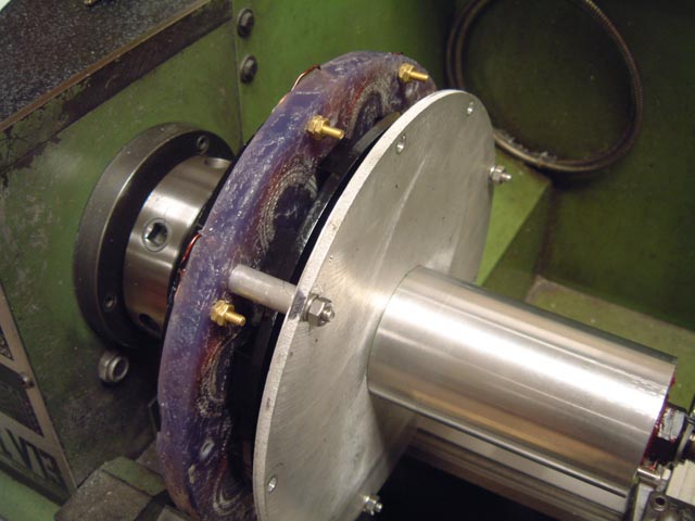
Here's a picture of my assembly going together.

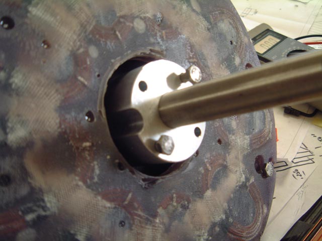
The cut out in the spacer are for the jack screws. I forgot to make the inside hole in the stator big enough so I had to improvise.
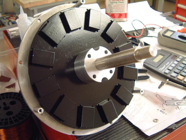


Here's a picture of the stator installed


After I completed the assembly I put it in the lathe for some initial tests.
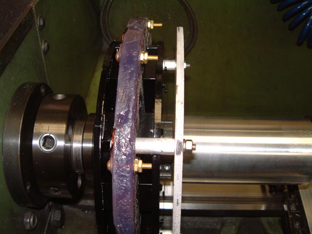


Here are the open volt:

RPM to Volts


  1. is 6.5
  2. is 10.9
  3. is 15.6
  4. is 19.0
  5. is 27.2
  6. is 31.6
  7. is 53.9
  8. is 77.1
  9. is 91.7
  10. is 127.2


I don't know if this is good or not but seems reasonable to me. I made the holes in the coils about 15 percent bigger than the magnets. I hope this "links" the coils properly.

I'm going to do a load test next to see what king of amperage it will put out. I think I will connect 50 feet of wire to it and then rectify it to 12 volts and see if there is any drop in voltage from directly on the generator to the end of the wire. I know that I will loose some in the conversion to DC power. I am hoping the cut in will be a little higher RPM that I am Currently getting.

I was a little surprised that I am getting the voltage out of this with a smaller magnet than most people are using.

I will post the results of the amperage test next week.


That all for now.

« Last Edit: August 18, 2006, 12:52:38 AM by (unknown) »

kitno455

  • Sr. Member
  • ****
  • Posts: 442
Re: Jensen Genny
« Reply #1 on: August 17, 2006, 07:13:26 PM »
good looking. the voltage you see is caused not only by the size of the mags, but also by the number of turns. if you cram a few thousand turns of microscopic wire in there, you could get a kilovolt while spinning by hand. but you could only get out a microamp or two of current :)


how are the mags attached? i see little dimples at each corner?


allan

« Last Edit: August 17, 2006, 07:13:26 PM by kitno455 »

tajim

  • Newbie
  • *
  • Posts: 14
Re: Jensen Genny
« Reply #2 on: August 17, 2006, 07:37:17 PM »
I machined pockets in them for the magnets to fit in.


« Last Edit: August 17, 2006, 07:37:17 PM by tajim »

harrie

  • Sr. Member
  • ****
  • Posts: 365
Re: Jensen Genny
« Reply #3 on: August 17, 2006, 08:02:34 PM »
Looks great, nice to have the tools to do the percision stuff, You may want to think about using a light color paint expecially on the rotors, due to the expansion and contraction from the sun, dark colors absorb heat, and will cause movement that could cause problems, just a thought. Thanks for shareing, Harrie
« Last Edit: August 17, 2006, 08:02:34 PM by harrie »

DanB

  • Global Moderator
  • SuperHero Member
  • *****
  • Posts: 2151
  • Country: us
    • otherpower.com
Re: Jensen Genny
« Reply #4 on: August 18, 2006, 07:57:26 AM »
Nicely done.  The voltage you get doesn't surprise me - I'm assuming the numbers you posted are AC (not rectified yet).  Normally we do about the same thing but our magnets are 1/2" longer and we'd be getting slightly higher open voltage using 70 turns of #14 gage wire - which I suppose we can attribute to a magnet which is 1/2" longer.


I think what you have here would be quite good for a 8 - 9' diamter 24V machine.

« Last Edit: August 18, 2006, 07:57:26 AM by DanB »
If I ever figure out what's in the box then maybe I can think outside of it.

Flux

  • Super Hero Member Plus
  • *******
  • Posts: 6275
Re: Jensen Genny
« Reply #5 on: August 18, 2006, 09:10:14 AM »
Yes I agree with Dan. Ideal for 8ft 24v.


Cut in just below 190 rpm for 24v. Furl at about 500W. You are about right with the 1 ohm resistance.


If for some reason you were thinking of 12v it is too slow, you would need to connect delta and possibly increase the air gap.


Line resistance will have no effect on your cut in speed, just affect the load in higher wind.


If you build the rest to the same standard you will have a nice machine.

Flux

« Last Edit: August 18, 2006, 09:10:14 AM by Flux »