Author Topic: Flat Span Coil  (Read 1140 times)

0 Members and 1 Guest are viewing this topic.

RogerAS

  • Sr. Member
  • ****
  • Posts: 329
Flat Span Coil
« on: September 26, 2006, 01:52:20 AM »
Hey All,


In the quest to build lower resistance and higher amperage output coils I've noticed several of you have started using 2, 3, 4 or more "in-hand" coils. I like that idea, and also sharing coil space among various wire gauges of those "in-hand" coils.


What about this?


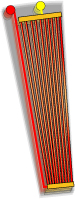
How about solid plates on the ends of the "coils" with straight segments of wire laid up in neat little rows touching the plates at each end. A layer of thin wire, a layer of electrically insulating substrate, a layer of thicker wire and another and another so on and so on. I would think soldering each layer would be a pain, but if ends could be left out of the coating/enamel a single row could all be joined as a unit.


Maybe make a jig to clamp the row of wire flat, burnish the ends, and solder on the "caps".


Would it be possible for some liquid to be highly conductive and cure to a solid, say when exposed to high intensity UV? If such exists I might be able to screen print these onto mylar or mica or??? and just keep stacking them layer upon layer.


If a single "span" line broke or burned the whole "span" might not fail.


Even if a human did/could splice thousands of ends that human might go insane. Some methods to automate laying the wire already exists. Small motion welder or whatever.


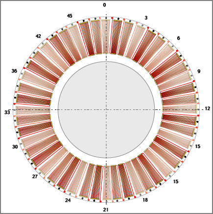
Width or "span" of these coils could be varied to fit your type of magnet(s), thin wedge magnets to match these "coils" would be a pain to find. I just went nuts with the idea. There could be far fewer "spans" for thicker/wider/longer magnets.


So, ???

« Last Edit: September 26, 2006, 01:52:20 AM by (unknown) »

stephent

  • Sr. Member
  • ****
  • Posts: 268
Re: Flat Span Coil
« Reply #1 on: September 25, 2006, 08:57:17 PM »
Howdy Roger..

You talking about something that looks like a hard drive cable with all wires joined at the ends? Which direction would they lay? Flat side to the mags or thin edge to the mags? Kinda looks like the printed circuit board "winding" someone had posted here a couple of weeks ago, but "hard-wired".

Looks like if you had enough of the ones shown in your pic, it would be possible to do a "wave" winding from one to the next "coil" in that phase.

Interesting concept--ribbon magnet wire.

Might try a trick I learned a while back--make a "ribbon" with mag wire using a flat board and some cheap finger nail polish--stick some small pin nails in a board close together and run the wire around them in a zig-zag pattern and then "glue" them together using the nail polish. Nail polish is very flexable when it dries--the more expensive stuff is anyway. Use wax paper or something to keep them from sticking to the board (I used wax--candle wax--just rubbed it on good). Made a flat 'ribbon" with #21 wire like you are talking about.

The stripping/soldering up at the ends was a "female dog", but possible.

I just wanted a flatter thiner connection coming from coil center. Ended up using a small length of thin, flat copper flashing, folded/doubled over the ends of the wire and just nail poilished it for insulation on a couple of 3 or 4 in hand test coils.

Yeah--yeah--I know--nail polish--but some of the pinks/reds ARE pretty and it goes on so slick and well --ON THE COILS--I only use it on the coils fellers/gals.....

Besides that--it's "recycling"--"using up"--"conserving resources"... what my wife doesn't like and won't use again.

« Last Edit: September 25, 2006, 08:57:17 PM by stephent »

DanG

  • Hero Member
  • *****
  • Posts: 1122
  • Country: us
  • 35 miles east of Lake Okeechobee
Re: Flat Span Coil
« Reply #2 on: September 26, 2006, 07:42:30 AM »
I think there is a reason you dont see any windings like that in use.. With so many adjacent parallel return paths for induced voltages it would exhibit a very low output if any - the conductor under the stronget lines of force would be short circuited by adjacent conductors that simualtaneously were subject to a weaker magnetic field.
« Last Edit: September 26, 2006, 07:42:30 AM by DanG »

SparWeb

  • Global Moderator
  • Super Hero Member Plus
  • *****
  • Posts: 5452
  • Country: ca
    • Wind Turbine Project Field Notes
Re: Flat Span Coil
« Reply #3 on: September 26, 2006, 12:25:13 PM »
You need a LOOP of wire.  The magnets have a field around them.  Each loop of wire encloses a portion of the field.  The flux inside the loop defines the "electromotive force" in the wire, which produces voltage.  I won't get into more detail here.  I don't see any closed loops in your diagram, just multiple parallel pathways.
« Last Edit: September 26, 2006, 12:25:13 PM by SparWeb »
No one believes the theory except the one who developed it. Everyone believes the experiment except the one who ran it.
System spec: 135w BP multicrystalline panels, Xantrex C40, DIY 10ft (3m) diameter wind turbine, Tri-Star TS60, 800AH x 24V AGM Battery, Xantrex SW4024
www.sparweb.ca

Chagrin

  • Full Member
  • ***
  • Posts: 195
Re: Flat Span Coil
« Reply #4 on: September 26, 2006, 05:50:21 PM »
It is a loop -- just a single loop.


But yes, I'll agree that it doesn't seem to be an efficient (power or manufacturing) design.

« Last Edit: September 26, 2006, 05:50:21 PM by Chagrin »