Author Topic: Two complete gennies  (Read 2620 times)

0 Members and 1 Guest are viewing this topic.

SparWeb

  • Global Moderator
  • Super Hero Member Plus
  • *****
  • Posts: 5452
  • Country: ca
    • Wind Turbine Project Field Notes
Two complete gennies
« on: October 23, 2006, 05:59:17 AM »
I completed my two generators, one axial, one a motor conversion, last month.  I'd begun slowly, but the projects both picked up speed at the same time, and there was some harmony in finding little things like fasteners that helped.


What I did recently finish was a written description the conversion.  I've linked to the document below.  I think I'll also post the contents in separate diaries, to allow searching.  I have only begun performance testing the conversion, so those results will be added later.


3HP 3 Phase Motor Conversion (1Mb)


The other interesting thing I did this weekend was experiment with motor-conversion cogging.  After a few attempts to illustrate the matter, I'm now in a position to demonstrate the phenomenon with my own.  I hope that the following explanation will help those who are new to the topic to understand the problem.


I started with magnets on all 12 faces of the rotor aligned with the axis.  No skewing at all.  Inserting the rotor and assembling the faceplate went fine, and when I attempted to turn the shaft by hand it was obvious what was going on.  I could rotate it one "step" at a time, 36 steps per revolution.


I then wrapped a string around the 1-1/4" shaft and pulled with a spring-scale.  It took 25 pounds to start the rotor turning against the first step.  Once it got going, it took 11 pounds to keep it going at a constant speed.


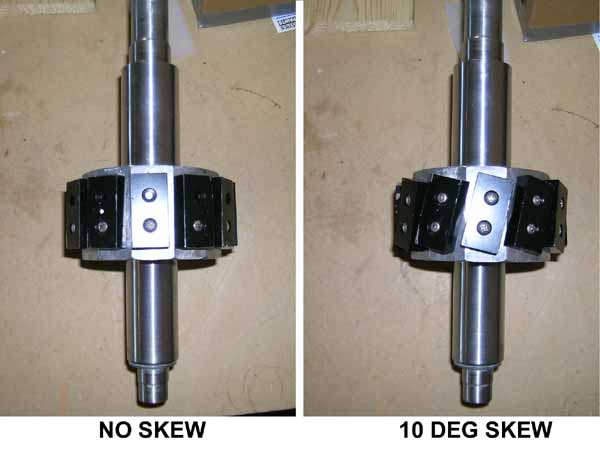
Later, I disassembled the rotor again and skewed all 12 magnets.  I fixed the skew angle at 10 degrees by tapping holes in each rotor face with a slant.  The 10 degrees refers to a view looking down the shaft of the rotor.  You can see one end of the magnet and in your mind's eye draw a line down to the axis.  You can also draw a line down from the back end of the magnet and it is turned 10 degrees away.  The 10 degrees works on a motor whose stator has 36 teeth (360 deg / 36 teeth = 10 degrees).  If your stator has 24 teeth, then your magnets need a (360/24) 15 degree skew.


I re-inserted the rotor with all skewed magnets and performed the same pull test.  The "steps" were much smoother, and to start the rotor took 14 pounds, and 8 to keep it going.  The starting torque has nearly been cut in half, and the running torque is also down by 1/3.


As a last test, I removed 4 magnets, leaving the remaining 8 skewed.  As expected, the pull test gave starting and running torque numbers 2/3 of the results with 12 magnets.  The extra torque required to start was never equal to the running torque, but I don't think there is a point where that occurs because even the bearings behave that way. I always takes a bit more oompf to get going, than to keep going.

« Last Edit: October 23, 2006, 05:59:17 AM by (unknown) »
No one believes the theory except the one who developed it. Everyone believes the experiment except the one who ran it.
System spec: 135w BP multicrystalline panels, Xantrex C40, DIY 10ft (3m) diameter wind turbine, Tri-Star TS60, 800AH x 24V AGM Battery, Xantrex SW4024
www.sparweb.ca

motoman465

  • Full Member
  • ***
  • Posts: 119
Re: Two complete gennies
« Reply #1 on: October 23, 2006, 05:16:42 AM »
Thanks, SparWeb.  I had an idea of what was meant about skewing from reading the other posts about it, but you really cleared it up.  I love the fact that you presented the before and after figures for torque.  Thank You!


Todd

« Last Edit: October 23, 2006, 05:16:42 AM by motoman465 »

ghurd

  • Super Hero Member Plus
  • *******
  • Posts: 8059
Re: Two complete gennies
« Reply #2 on: October 23, 2006, 08:35:48 AM »
One motor & 2 rotors?

It would be interesting, at least to me, if when everything is done... Turn the unused one down to round leaving the magnets in the same place.  Then see how cogging and output change.


Round I can do, but flats take a long time with a file. :(

Nice write-up.

G-

« Last Edit: October 23, 2006, 08:35:48 AM by ghurd »
www.ghurd.info<<<-----Information on my Controller

SparWeb

  • Global Moderator
  • Super Hero Member Plus
  • *****
  • Posts: 5452
  • Country: ca
    • Wind Turbine Project Field Notes
Re: Two complete gennies
« Reply #3 on: October 23, 2006, 08:46:52 AM »
Yer welcome.
« Last Edit: October 23, 2006, 08:46:52 AM by SparWeb »
No one believes the theory except the one who developed it. Everyone believes the experiment except the one who ran it.
System spec: 135w BP multicrystalline panels, Xantrex C40, DIY 10ft (3m) diameter wind turbine, Tri-Star TS60, 800AH x 24V AGM Battery, Xantrex SW4024
www.sparweb.ca

SparWeb

  • Global Moderator
  • Super Hero Member Plus
  • *****
  • Posts: 5452
  • Country: ca
    • Wind Turbine Project Field Notes
Re: Two complete gennies
« Reply #4 on: October 23, 2006, 08:53:25 AM »
Sorry, Ghurd, I was getting ahead of myself and that's led to some confusion.  In another diary entry I detail the axial flux alternator I've built, but this post is really only about the motor conversion.


I only built one rotor for it.  There was a brief consideration of two rotors for comparative testing, but that was abandoned partly due to the work involved, also partly due to clumsiness on my part (sorry T.S.)


I have access to a machine shop through work.  Not everyone's so lucky.  Still, I doubt that attempting the same experiement with a round rotor would produce results any different.


Also, note that I could put two hole in diagonal locations on the flat faces.  That is much harder to do if the rotor is round and the drill bit is slipping down the side as it starts to drill in... minor point.  The day I saw how Zubbly built his rotor, I know I could make mine almost the same, AND skew the mags no problem.

« Last Edit: October 23, 2006, 08:53:25 AM by SparWeb »
No one believes the theory except the one who developed it. Everyone believes the experiment except the one who ran it.
System spec: 135w BP multicrystalline panels, Xantrex C40, DIY 10ft (3m) diameter wind turbine, Tri-Star TS60, 800AH x 24V AGM Battery, Xantrex SW4024
www.sparweb.ca

ghurd

  • Super Hero Member Plus
  • *******
  • Posts: 8059
Re: Two complete gennies
« Reply #5 on: October 23, 2006, 09:26:37 AM »
"only built one rotor"  Smart!


I was wondering how flat neos on a round rotor changes things.

« Last Edit: October 23, 2006, 09:26:37 AM by ghurd »
www.ghurd.info<<<-----Information on my Controller

Darren73

  • Jr. Member
  • **
  • Posts: 98
Re: Two complete gennies
« Reply #6 on: October 23, 2006, 02:07:48 PM »
Guard, what machines do you have access to?


Regards

Darren

« Last Edit: October 23, 2006, 02:07:48 PM by Darren73 »

ghurd

  • Super Hero Member Plus
  • *******
  • Posts: 8059
Re: Two complete gennies
« Reply #7 on: October 23, 2006, 02:50:08 PM »
Me? (close enough)  

The $350 'you-get-what-you-pay-for' HF mini-lathe, small drill press...

Once a year welder. Mo mill, no rotary table, etc. And no machine shop willing to do anything like this.

G=

« Last Edit: October 23, 2006, 02:50:08 PM by ghurd »
www.ghurd.info<<<-----Information on my Controller

Darren73

  • Jr. Member
  • **
  • Posts: 98
Re: Two complete gennies
« Reply #8 on: October 23, 2006, 03:33:12 PM »
Apologies Ghurd,

the mini lathe can be used as a mini mill, mount the cutter in the chuck and clamp the work to the cross slide, i'm sure someone of your ingenuity will have no problem with this, keep the feed slow and put a piece of Perspex between you and the cutter


take care

Darren

« Last Edit: October 23, 2006, 03:33:12 PM by Darren73 »

dinges

  • Hero Member
  • *****
  • Posts: 1294
  • Country: nl
Re: Two complete gennies
« Reply #9 on: October 23, 2006, 03:43:29 PM »
Interesting, Steven!


Seems you've beaten me. My 3hp is still in the same stage it was in 3 months ago :)


I was surprized it still cogged when skewed (but, less cogging than unskewed, of course). Until I realized: the angle that you set the magnets at, is that 10 degrees?


You may remember our discussion on angles we had 4-5 months ago. How 10 deg in one plane does translate to a different angle on the face of the rotor. In my conversion, about 4 deg.


It would be interesting to see if, when the magnets are mounted at the 'correct' angle (my guess: 3-4 deg), all cogging would disappear... I think it would not cogg but it's not easy to implement on your rotor (the tapped holes would overlap, I assume)


BTW, how about the 'sogginess', i.e. iron losses of the rotor? Can you give an estimate of that? Or is the cogging masking any sogginess that may be present?


I'll be following your escapedes with interest.

« Last Edit: October 23, 2006, 03:43:29 PM by dinges »
“Research is what I'm doing when I don't know what I'm doing.” (W. von Braun)

dinges

  • Hero Member
  • *****
  • Posts: 1294
  • Country: nl
Re: Two complete gennies
« Reply #10 on: October 23, 2006, 03:47:46 PM »
you can see here how I measured sogginess on my mini-induction conversion. But, this method can probably only be used when there's (practically) no cogging...


http://www.fieldlines.com/comments/2006/8/12/213549/997/26#26

« Last Edit: October 23, 2006, 03:47:46 PM by dinges »
“Research is what I'm doing when I don't know what I'm doing.” (W. von Braun)

vawtman

  • Hero Member
  • *****
  • Posts: 1425
Re: Two complete gennies
« Reply #11 on: October 23, 2006, 05:34:40 PM »
Ghurd heres a pic of an idea i had awhile back


The weird thinking was that i could skew the lams just right and has one jumped the other would push.


 Im just putting it on hold for awhile and sure the losses would still be there.For now anyway.


 The lams would be separated to match the rotor widths.

« Last Edit: October 23, 2006, 05:34:40 PM by vawtman »

vawtman

  • Hero Member
  • *****
  • Posts: 1425
Re: Two complete gennies
« Reply #12 on: October 23, 2006, 07:40:19 PM »
Steve i think it would be nice if you gave Zubbly a little plug in there somewhere.Since you learned this from him.Just a thought
« Last Edit: October 23, 2006, 07:40:19 PM by vawtman »

SparWeb

  • Global Moderator
  • Super Hero Member Plus
  • *****
  • Posts: 5452
  • Country: ca
    • Wind Turbine Project Field Notes
Re: Two complete gennies
« Reply #13 on: October 23, 2006, 08:35:06 PM »
Read my last post... " The day I saw how Zubbly built his rotor, I know I could make mine almost the same, AND skew the mags no problem."  Credit has already been given where it's due.


But I'm not afraid to repeat it.  Thanks Mr. Z! :^)

« Last Edit: October 23, 2006, 08:35:06 PM by SparWeb »
No one believes the theory except the one who developed it. Everyone believes the experiment except the one who ran it.
System spec: 135w BP multicrystalline panels, Xantrex C40, DIY 10ft (3m) diameter wind turbine, Tri-Star TS60, 800AH x 24V AGM Battery, Xantrex SW4024
www.sparweb.ca

SparWeb

  • Global Moderator
  • Super Hero Member Plus
  • *****
  • Posts: 5452
  • Country: ca
    • Wind Turbine Project Field Notes
Re: Two complete gennies
« Reply #14 on: October 23, 2006, 10:30:33 PM »
Hi Peter,


I should have said it was a race!  You've definitely been quite busy, now that I read the rest of your mini-conv thread.

I'm interested in running some more tests on the motor conversion - I already have everything I need to get a few numbers - but I want some rigour, and that takes a bit of planning.


To start, I haven't seen the term "iron loss" defined yet.  Taking a motor conversion like mine, I have two inputs and two outputs:  Torque and RPM in; Volts and Amps out.  If under some V and A load conditions I can turn the rotor at a particular RPM, then there will be a specific torque associated with that.  I have no way, however, of deciding where the power loss has gone.  All I know is that I have put in X watts, and gotten some fraction less watts out.  In a motor conversion, there are two bearings, each with their own loss due to friction (not negligible).  There is also a loss due to the cogging effect making a magnet hard to pull away from the nearest stator tooth, but most of it is recovered as the magnet jumps toward the next tooth.  There are other losses that are very small, such as flux linkage with parts of the rotor shaft and housing that don't put a flux line through a coil.  If there is also a loss due to "domains changing polarity" in the thin laminates, then so be it, but I cannot tease that quantity out of the sum of all losses.


My drill press, as I stated above, is rated at 1/2 HP (373W).  Any load that poses enough resistance will force the motor to slow down; it will not operate above its rated power (approximately).  If the torque is such that any belting arrangement is slowed to, say, 500 RPM, then I can work out the torque that was applied.  I encountered this already in earlier tests and I have derived a few data points this way.  Not enough to make a curve.  I will use a lathe at work after I've done a few more practice runs on my drill press.  I want to test not only open circuit voltage but also a series of fixed resistances at various speeds, battery charging at various speeds, and also repeat said tests with different Star, Delta, series and parallel connections.  8 suites of tests, in all.  It will take an entire day at the shop, hence a free weekend.


This will also have to wait until after I buy or build an ammeter.  I've been blowing enough multimeter fuses that I've paid for an ammeter twice over already.


I still don't accept your "correct" angle for de-cogging, but it may only be a mis-matched frame of reference.  I won't pick up the gauntlet.  Repeated re-assemblies of my conversion have caused much wear-and tear on the magnet surfaces.  I will risk one last disassembly to apply a coat of paint and loctite to the screws before it's buttoned up for good.  I have satisfied myself, and ultimately you will have to satisfy yourself, too, when it is time.


Thanks again, Dinges.  My thinking has clarified a bit while writing this response to your suggestions.

« Last Edit: October 23, 2006, 10:30:33 PM by SparWeb »
No one believes the theory except the one who developed it. Everyone believes the experiment except the one who ran it.
System spec: 135w BP multicrystalline panels, Xantrex C40, DIY 10ft (3m) diameter wind turbine, Tri-Star TS60, 800AH x 24V AGM Battery, Xantrex SW4024
www.sparweb.ca

Flux

  • Super Hero Member Plus
  • *******
  • Posts: 6275
Re: Two complete gennies
« Reply #15 on: October 24, 2006, 12:42:31 AM »
Iron loss is the combined loss due to core eddy currents and core material hysteresis loss. You will not be able to separate them.


You measure iron loss with no load. You should easily be able to measure torque if you drive the thing between centres on the lathe and measure the torque trying to turn the stator with a spring balance ( or load cell if you have one)


It would be well worth taking the trouble to measure torque so that you can measure iron loss and total loss at each speed.


We have lots of data on power out, but as far as I can remember, no one has measured power in, to determine efficiency.


I know what figures to expect for the type of machines I have built but I have never tried a slotted core machine with neos.


Years ago I did a lot of tests with slotted core and wound fields with solid iron pole shoes. These always showed very high iron loss that would have delayed start up if the field was applied at start. Some of this would be due to surface loss induced in those solid iron poles. It would be nice to know what proportion is true core iron loss and what is surface loss in the pole shoes. Neo will have low or negligible induced loss compared with those iron pole shoes.


The fact that no one seems to have start up trouble with these motor conversions makes me think that the surface loss in the poles may have been more than the true core loss.


Machines that I built with Alcomax magnets and iron pole shoes were reluctant to start and cogging was not the main issue, that could be reduced to virtually zero by careful skew. ( not the theoretical angle).


The sogginess that Peter refers to is the iron loss. For the iron poled alcomax magnet machines, it felt as though the thing was full of treacle when you turned it.

Flux

« Last Edit: October 24, 2006, 12:42:31 AM by Flux »

dinges

  • Hero Member
  • *****
  • Posts: 1294
  • Country: nl
Re: Two complete gennies
« Reply #16 on: October 24, 2006, 04:43:58 PM »
"I still don't accept your "correct" angle for de-cogging, but it may only be a mis-matched frame of reference.  I won't pick up the gauntlet."


No worries, I wasn't really asking of you to prove my ideas/theories. I will be doing that myself very soon. In the worst case I'll have a slightly cogging rotor, but I doubt it will cogg. Then again, I've been known to be wrong. There was that one time back in '85...


As you have seen, the Jacques-M method I used on the mini-induction conversion is absolutely totally cogless. So, it can be done. The downside is it needs balancing, preferably dynamic balancing ('spin balancing'). I'm sure that Zubbly's way of converting, very slightly modified, will yield predictable, repeatable cogless conversions as well. But I'll be able to tell soon, hopefully.


I'm still not sure whether you've used the right angle (10 degrees; but, in what plane of reference). If your magnets make an angle of 10 deg with the longitudinal axis of the rotor, then I'm sure the angle is 'wrong'. 'wrong' as in not meaning bad, but it could have been better.


</sermon>


Flux is right, I meant iron losses with my 'sogginess' remark. Sogginess best describes how it feels to turn the rotor. As for bearing losses, etc., I assume these to be negligeable. At worst 2% or so per bearing. Fiddling in the margin, IMHO. If my calculations are within an order of magnitude of the real thing, I'm happy. Safety factors take care of the rest... ;)


BTW, if you get or build yourself a shunt, you could measure voltage over the shunt instead of current, with the DMM. Usually, my test leads blow up before the fuse does. Maybe that's because the 20A range of the DMM is unfused...

« Last Edit: October 24, 2006, 04:43:58 PM by dinges »
“Research is what I'm doing when I don't know what I'm doing.” (W. von Braun)

vawtman

  • Hero Member
  • *****
  • Posts: 1425
Re: Two complete gennies
« Reply #17 on: October 24, 2006, 05:47:28 PM »
Steven, Zubbly skewed the stator and you should also if if your going to use that style mag.Maybe you could skew the rotor flats.I feel you would have an airgap problem by skewing those mags on straight surface. Wouldnt you?

 What outputs are you getting from the skewed version or just demonstrating the principles?

 Or did i miss something again?

 Your idea is good to show newbies it would have helped me a great deal early on.

 Nice work
« Last Edit: October 24, 2006, 05:47:28 PM by vawtman »

SparWeb

  • Global Moderator
  • Super Hero Member Plus
  • *****
  • Posts: 5452
  • Country: ca
    • Wind Turbine Project Field Notes
Re: Two complete gennies
« Reply #18 on: October 25, 2006, 01:08:44 PM »
V,


You didn't miss anything.  By skewing the magnets, the corners start to get closer to the stator teeth.  In order to maintain a safe clearance, I actually have a smaller rotor to mount the magnets.  Slightly smaller.  Given all the iron in the stator, I doubt there are many missed flux lines.


My cog test only demonstrated "the principle".  I wasn't measuring anything else.


Lastly, to prevent any further confusion, you repeated something stupid I said a few months ago.  Flats machined onto a cylindrical surface can't be skewed.


...but the screw holes can.  Just another way to skin this cat.

« Last Edit: October 25, 2006, 01:08:44 PM by SparWeb »
No one believes the theory except the one who developed it. Everyone believes the experiment except the one who ran it.
System spec: 135w BP multicrystalline panels, Xantrex C40, DIY 10ft (3m) diameter wind turbine, Tri-Star TS60, 800AH x 24V AGM Battery, Xantrex SW4024
www.sparweb.ca