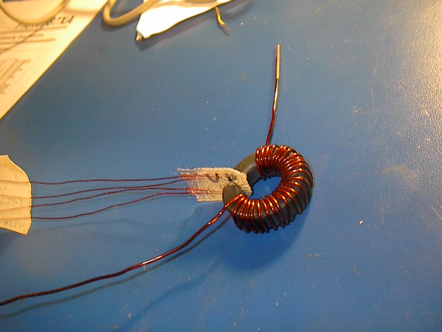
the first shot is my hall sensor , with a coating of fiberglass (epoxy) over the actual sensor, to keep it from bending or breaking the wires
i cut a slot on the ferrite ring to fit the sensor in . just like Jim did

there are about 25 turns of 0.045"dia wire on the ring
i ground the burrs(from the manufacturing process) off the ring to keep it from shorting out the turns
the Voltage output of the sensor is proportional to the flux the sensor sees
somone with a fluxmeter could correlate the readings i got (so i could read the output in tesla(not required but might be fun and interesting)
like if for instance with 2.12A going through the 25 turn coil , it was reading 332milli Volts , just about half scale , because the sensor puts out 638mV when under or in the magnetic field of my minigens magnets
i suppose it might go higher if i was to put over 4A through the coil , but i have not tried that yet.
...I(A)...V(mV)
.005--14.4
.31-- 57.3
.52-- 94
.6--- 107
.81-- 139
1.05- 175
1.32- 217
1.61- 260
2.12- 332
i graphed the data and the curve was a straight line , so i extended the graph to read ~ .638V and it came out to ~ 4Amps
so with the sensor on the output of the minigen , boosted to ~25Volts and 4Amps readable current , i should be able to measure 100 watts output from the minigen,i hope that its not to optimistic:)
http://www.otherpower.com/images/scimages/2965/Picture_060.jpg
the second shot is the RS232 cable connected to the pic u controller i made it a clickable link because of the size~135KB
