Author Topic: Alternator Assembly - Day One  (Read 1080 times)

0 Members and 1 Guest are viewing this topic.

wil

  • Jr. Member
  • **
  • Posts: 57
Alternator Assembly - Day One
« on: January 13, 2007, 10:51:27 PM »
Assembling the alternator was a bit of an adventure and the anticipation of seeing some voltage output was killing me!


Ok now lets see what a few magnets and some coils of wire can do....


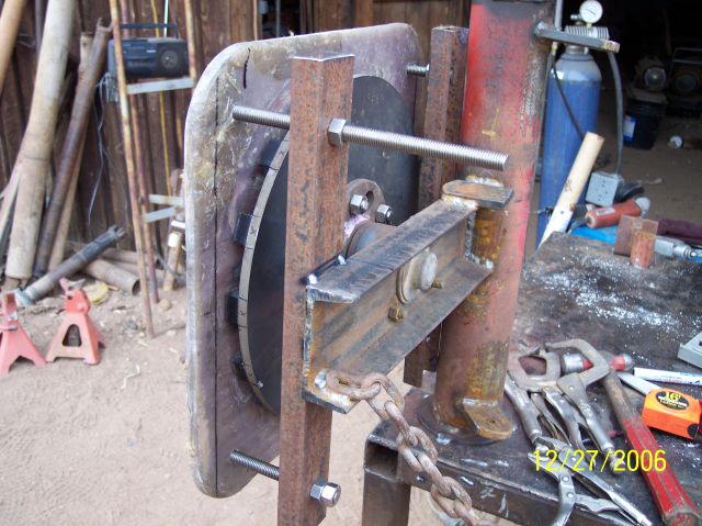
First I needed to build a stator mount. The mount in Hugh's plans seemed a little complicated. I wanted something a little easier and needed to stick to the philosophy of the master plan - K.I.S.S. (Keep It Simple Stupid)


The stator mount is just tacked into place at this point. I didn't want to weld'er solid until I was certain it was in the right place.


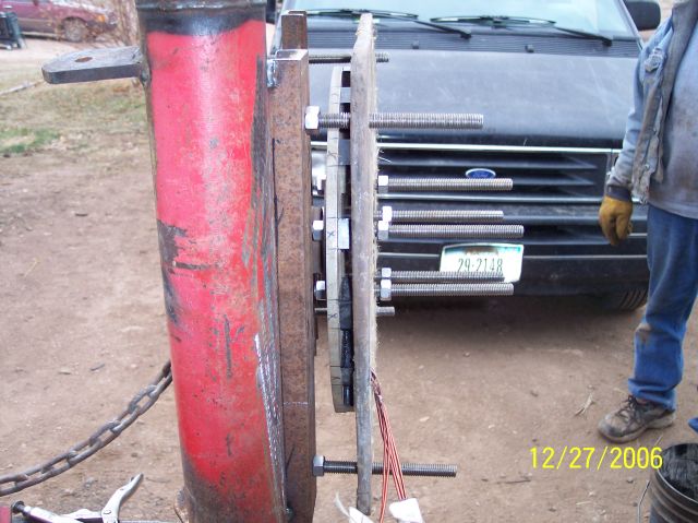
Here is a side shot of the mount. You can also see a portion of my father who has been indispensable throughout the whole process. After all he is the one who taught me the basics of welding, mechanic'in and running a lathe.


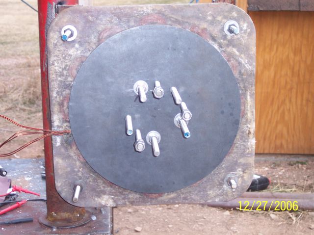
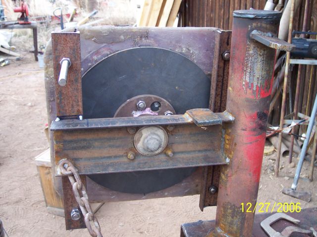
Ok - Couldn't wait any longer I had fasten the stator down and install the front magnet plate. (What will it do for voltage - keeps ringing thru my mind!)


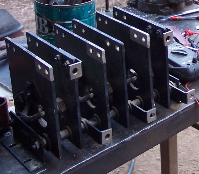
This is the stud diode rectifire that I scrounged from an old piece of mining equipment. I'm not sure what the ratings are on these diodes but I'm sure it's more than I will need.


I decided to install the rectifier after I seen that the alternator was showing some voltage from leg to leg. At this point the amount of voltage was not important, but rather the fact that it is producing a voltage.


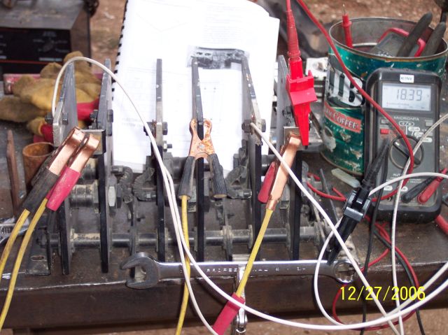
Ok - I know this is messey...but you have to realize the need that I was experiencing to see this thing work.


All we had were some jumpers and....Well a 3/4" wrench to make some connections. :)


HA - 18 VDC! She works...


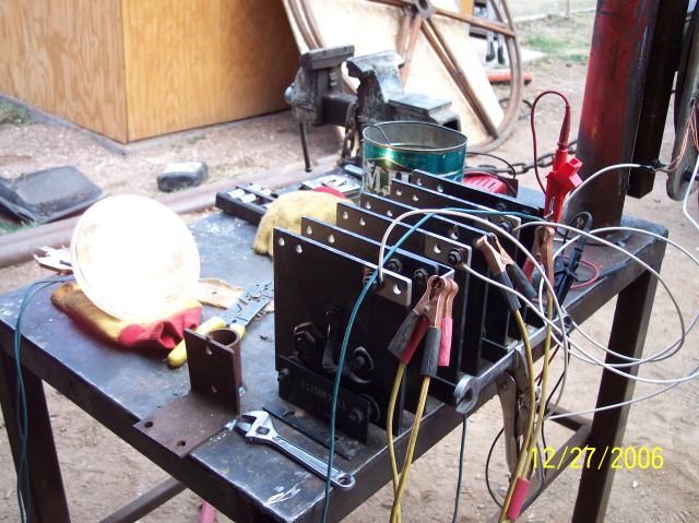
Ok, ok... yeah but it's not doing anything right. What can we use for a load. Well we scrounged an old head lamp and pig tail from an old Chevy Nova and made'er light-up.


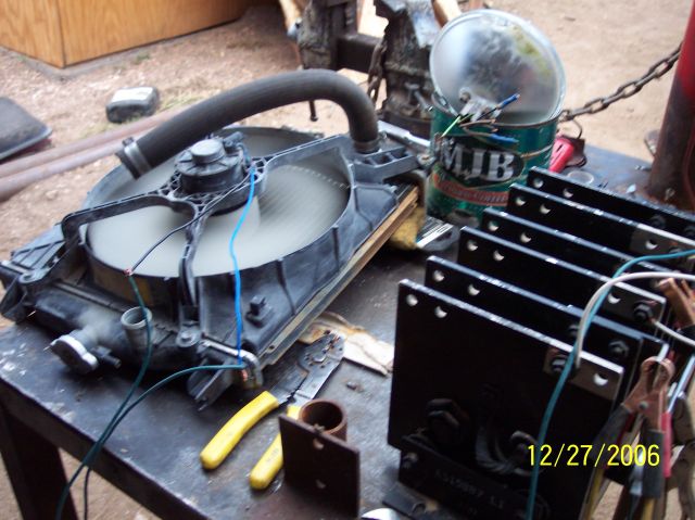
The next "load" we found was a coolant fan scavanged from a Subaru. We knew that sooner or later these old car parts were going to come-in handy!


I'm not sure how the fan motor is constructed but it didn't take much to make her spin. In fact a quarter of a turn on the alternator would make the fan start to spin! That was neet..


Incidentally, the head lamp that is now setting in the old coffee can has an element that is burnt-out.  We thought it would be fun to see if we could fry it...we did.


It's amazing how, when loaded, you can feel the torque on the alternator. Also, when you short all three of the legs together before the rectifier, the torque is tremendous.


After the new excitement died down, I took another look at the air gap between the magnets and seen that it was not very uniform. At one extreme there was about an 1/8" between the stator and magnet plate and on the other end there was about 1/4" gap.


Well, that was it for day one of the alternator's assembly. The next day was going to be a time for making sure the air gap between the magnets was more uniform, make better connections on the rectifier and to take some meaningful voltage and speed (rpm) measuements.


Wil

« Last Edit: January 13, 2007, 10:51:27 PM by (unknown) »

RP

  • Hero Member
  • *****
  • Posts: 722
  • A dog with novelty teeth. What could go wrong?
Re: Alternator Assembly - Day One
« Reply #1 on: January 13, 2007, 04:52:34 PM »
Congratulations!


I like that rectifier assembly.  Can you tell us more about it?  Are those aluminum plates or steel?

« Last Edit: January 13, 2007, 04:52:34 PM by RP »

wil

  • Jr. Member
  • **
  • Posts: 57
Re: Alternator Assembly - Day One
« Reply #2 on: January 13, 2007, 05:48:57 PM »
Well, I'm not 100% sure of it's construction.


I know it's not aluminum because it's quite heavy. So it is either steel or tinned copper.


It came from some surplus mine machinery components. It was either an old Dragline or Shovel, but more likely a Dragline.


I thought the guy said the diodes were rated for 200 amps but that may not be correct. I cant see any markings on them because they have been coated with an insulating paint of somekind.


Wil

« Last Edit: January 13, 2007, 05:48:57 PM by wil »

jlt

  • Sr. Member
  • ****
  • Posts: 368
Re: Alternator Assembly - Day One
« Reply #3 on: January 14, 2007, 09:42:14 AM »
It sounds like you have a bad case of fireitupitus.I suffer from the same thing.i am building one very similar to yours. only mine is 48 volt.Looking at your picture It looks like the the blades will be too close to the tower.make sure you have aprox. afoot of space. The blades bend back a lot in high winds. Just my 2cents                 jlt
« Last Edit: January 14, 2007, 09:42:14 AM by jlt »

wil

  • Jr. Member
  • **
  • Posts: 57
Re: Alternator Assembly - Day One
« Reply #4 on: January 14, 2007, 11:44:05 AM »
Hi jlt,


Yours is the second comment on the blades hitting the tower. You guys have me worried...


I quickly drew the machine on CAD and it looks like I will have approximately 9" from the tip to the tower.


Are you saying a foot would be the safest distance?


It's still on the ground and I can still move things around so now is the time to make changes like this.


Thanks,


Wil

« Last Edit: January 14, 2007, 11:44:05 AM by wil »

RP

  • Hero Member
  • *****
  • Posts: 722
  • A dog with novelty teeth. What could go wrong?
Re: Alternator Assembly - Day One
« Reply #5 on: January 14, 2007, 12:06:21 PM »
It looks like your bearing hub is bolted on.  


You might consider making a little "wedge" spacer to put between the hub and the channel iron.  It wouldn't take much to move the blade tips out a little bit.  The stator support bolts should give you enough adjustment to keep it in line with the rotors.

« Last Edit: January 14, 2007, 12:06:21 PM by RP »

wil

  • Jr. Member
  • **
  • Posts: 57
Re: Alternator Assembly - Day One
« Reply #6 on: January 14, 2007, 01:43:51 PM »
Yes the hub is bolted.


I just took some measurements to get a more accurate look at what was happening.


Above I guessed at 9" but after taking some measurements it looks like there will be 8" of clearance between the tip of the blade and the tower.


One other thing I could do is shim the blades out depending on how far the tips need to be from the tower. Although a wedge under the bottom of the hub might move it farther away.


Wil

« Last Edit: January 14, 2007, 01:43:51 PM by wil »

wil

  • Jr. Member
  • **
  • Posts: 57
Re: Alternator Assembly - Day One
« Reply #7 on: January 14, 2007, 02:29:28 PM »
If I need to shoot for 12" between the tip of the blade and the tower, it looks like the best bet is placeing an 1/8" shim under the bottom of the hub.


On the 4 degree angle I will have approximately 8" from tip to tower.


On a 6 degree angle I will have approximately 12" from tip to tower.


The difference between the two is .113", so an 1/8"(.125) shim should work.


Wil

« Last Edit: January 14, 2007, 02:29:28 PM by wil »