Hello all,
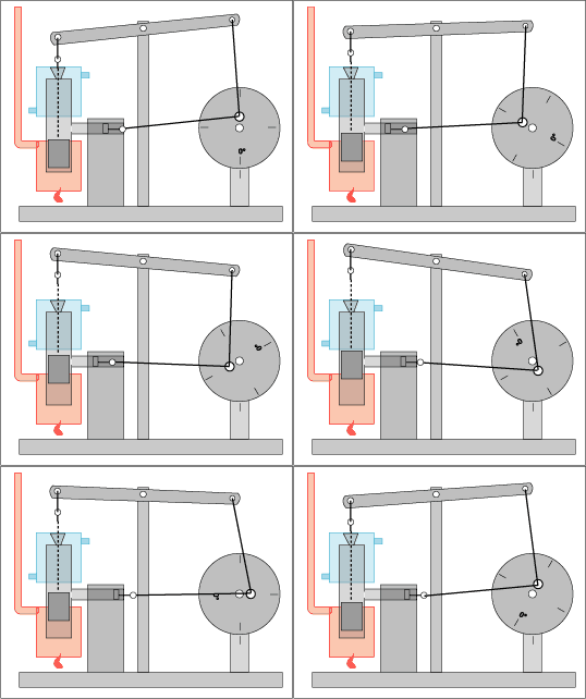
Above, if allowed through to the board, is a walking beam stirling engine modeled on the ones over at:
http://www.boydhouse.com/stirling/htmlstirlingplans/index.html
Yes I did the animation, Illustrator, Image Ready, no biggie. The Illustrator vector files have measurements and are to scale if anyone can use 'em just ask. I wish I had some good 3d modeling software!
I've developed a notion that scaled up and multiplied these things might start contributing to power production. Rider Ericsson (sp?) water pumpers were made until the 30's, what I wouldn't give for one of them! Basically this is a simplified version of one of those engines. Some of those had 8" displacer cylinders! I think I'll try the one shown here first with a 2.625" dia :-)
Displacer piston = up and down
Power piston = back and forth
I lean back a really heave my lure out into the lake, hoping for a bite.
Wouldn't a copper displacer cylinder work better than a steel one? Does anyone make large (3"+) diameter stiff copper pipe? Would brass work almost as good for heat transfer? What about Aluminum? Sources??
With really good heatsinks could the water tank(upper blue-ish thing) go bye-bye?
What about a "O" ring sealable flanged head where the displacer rod exits for easy bushing replacement?
Low friction bushing matrial, besides brass, for the displacer piston rod, suggestions? Ideas?
What about the displacer piston face(s) contours being optimized for the cool and hot side? Would one end being cupped and the other bulging make a difference? If so which way for what?
Super low friction rings or a piston design for the power piston to maintain a good seal?
What about VCR head motor bearings for the pivot points? Better bearings, options?
Would an aluminum can pair of bottoms make a better displacement piston than a steel sauce can, even if the beer cans have to be jb welded to make the piston? (given a proper air gap between piston and cylinder). What else would be light sturdy and heat resistant?
Should the blancing of the engine follow a procedure such as?:
1. Flywheel 2. Walking Beam 3. Displacer Connections 4. Power Piston Connections
Other options here?
If power is taken via a belt, should it be in a small diamer pully near the crank or the outside of the flywheel or somewhere in between?
What about enclosing the whole thing within a helium sandwich?
The top piece of "bread" is a brass or copper plate with a set of holes around the rim about 1" apart. This piece of "bread" is the radiator for the cool side and is mated to the top of the displacer cylinder. This plate will be slightly wider than the "meat" diameter. A pyrex ring of glass larger in diameter but the same height as the engine. That is the "meat", and sealing this to a bottom plate, which is the bottom pece of "bread". Make some of the bolts that hold the sandwich together long enough to get a heat source under the displacement cylinder, which is now attached to the bottom piece of "bread". Think banjo head. Feed the electrical power lines through a ceramic/silicone plug in the top piece of "bread". Place a propane tank valve on this top plate to allow pressuization of helium monitored with a tapped and sealed gauge. An adaptor for the easy to get balloon helium bottles could be made up 'cause you gonna lose helium no matter what and need to refill.
If it needed maintainance the bolts cane be undone and new O rings installed. The bottom plate might be expoxied to the glass cylinder with O ring seal(s) for the top.
Crazy, I say!
Yeah, I know, but just how serious is it?
We won't know until all the tests results are back, but it doesn't look good.
Tell me about it! Do you think he's dangerous?
No, but we'll sedate him anyway just to be sure.