Following my last rather poor start at testing, I managed to rig up a motor to drive the rotor assembly so that I could do something a little more accurate. Spinning the thing by hand and trying to count the turns just wasn't the way to go!
A small DC motor run from a Lab power pack gives me adjustable speeds, and seems to be quite repeatable; if I dial up the same voltage I get around about the same RPM.
Here is a picture of the 'scope with a 50 turn coil attached.
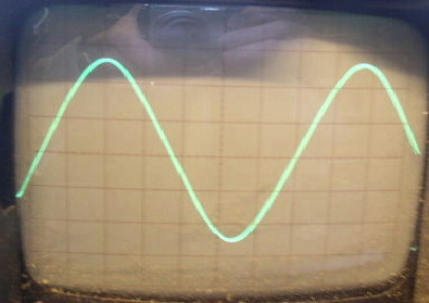
This shows about 3.5v at the top of the peak, and the time-base gave about 300 rpm.
(1 volt per division, and 5ms per div)
I get the feeling that this isn't enough voltage for what I want to do, and that I will need some more turns on the coils. I'm planning on 4 ft diameter blades on this, and from what I can work out, it will be bearly cutting in untill 300rpm to charge 12v.
Just for interest, I spent a little time using Exell spreadsheet, and plotted a sine wave. I've overlaid this on my scope picture and got a fairly good match. I can't display it here, but please have a look at my photo uploads for a 'sine.doc'.
Other figures from my test...
- rpm gave 4v
- rpm gave 5v.
More to follow when I get my camera recharged.
