Continued from
http://www.fieldlines.com/story/2007/5/21/53352/2751
The picaxe and associated circuitry I described in the last post is similar to a number of units I’ve made in the past and actually forms part of the controller I’m developing so was conveniently already available. There is maybe $20 worth of parts involved. This unit takes its power from the attached 12V or 24V battery for which I have used a pair of jumper cables with one set of clips removed to attach to the terminal block. The serial data is sent to the laptop via the 3.5mm stereo jack and suitable cable via a USB-Serial adaptor. This is the same connection that is used to program the picaxe. The phase connection for RPM measurement gets attached to one of the three incoming conductors from the turbine – either attached to the controller that comes with the turbine or to my own rectifier. The rectified output from the turbine goes to the T- and T+ connection on the terminal block.
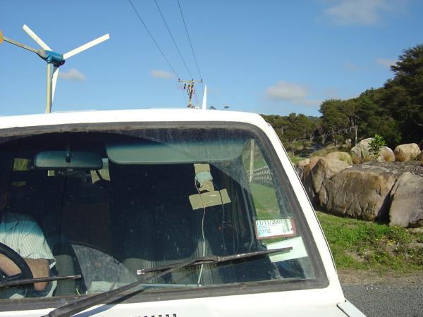
The GPS unit requires 5Vdc to operate so I cut up a USB cable and took the 5V supply from a spare USB port on the laptop. As it is reasonably small and fragile I have taped it to the windscreen of the vehicle.
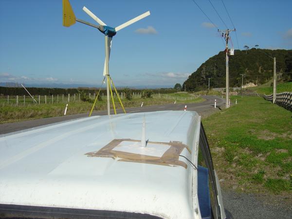
The GPS requires an antenna – preferably mounted external to the vehicle. To achieve this I simply cut back a section of coax to expose the centre conductor to give a simple dipole antenna. The excess shielding is taped to the roof of the vehicle to form a ground plane and the centre conductor is poked up the nozzle of a calking gun cartridge. The nozzle in turn is poked through a 10l plastic paint pail lid to keep the antenna vertical. The whole lot is taped to the roof. Pretty low tech but serviceable antenna and I often have a lock on 8+ satellites. The GPS is also connected to the laptop via a USB-Serial adaptor.
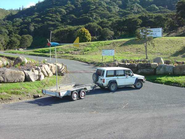
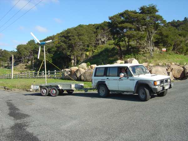
It was pretty straight forward mounting the turbine on the trailer. These turbines come with a base plate for mounting the tower that have two holes predrilled for pinning them to the ground (entirely inadequate for normal use) that I have used to bolt to the steel deck of my trailer. The standard 4m tower comes in three sections that simply slide together. I have left out the centre section to limit the height above the trailer. I have used ratchet tie downs to guy the tower. The pole is mounted on a single pivot pin in the base and the whole setup including turbine can be lifted straight up into position by one (reasonably strong – the turbine is approx 50Kg) person. The cable from the turbine is simply run in the rear door of the vehicle (through a convenient gap in the rubber seal) and connected to the equipment in the back.
The software for the picaxe is very simple as all calculations are done in the software on the laptop. The program basically reads the three inputs, outputs the data to serial port then repeats. You can download the code here: http://www.otherpower.com/images/scimages/2210/TurbMon.bas The circuit I described is all that is required to program the picaxe chip – no programmer board is required.
The software on the laptop is written in VBA in Excel. Pressing CTRL+R in any worksheet brings up this dialog box

Because the com port number changes depending on which USB port the adaptor is plugged into, it is most convenient to have these fields available. After specifying the ports the raw data from both the GPS and the picaxe is visible in the GPS and Turbine textboxes. As soon as the information is available, the fields at the bottom of the dialog box display readings at 1 second intervals. The GPS sends data at 1 second intervals while the picaxe sends data at least 3 times a second but typically faster depending on the RPM of the turbine. The display of all the information is triggered by the receipt of GPS data with all the readings from the picaxe since the last transmission are averaged. The GPS data consists of NMEA ‘sentences’ terminated by CR LF. Each sentence has a heading followed by a varying amount of comma separated data. The sentence of interest here is $GPRMC which among other things has the time(UTC) and speed in knots. Information regarding NMEA can be found here: http://www.gpsinformation.org/dale/nmea.htm. Pressing the Start button will start the program writing data to the current worksheet at one second intervals, starting at row 10 and appending down until the user hits Stop.
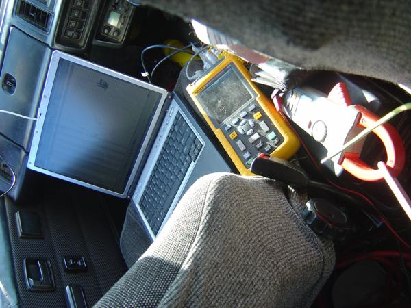
Once everything was in place I was rather keen to see the turbine flying so I bypassed my initial intention of doing a few runs with the anemometer attached and put the turbine straight up. Unusually there were no glitches in the system and the data started coming through straight away. For calibration purposes I hooked the turbine up via my own rectifier direct to a reasonably dead car battery (or two for higher voltage). As well as the picaxe monitoring I used a Fluke Industrial Scope Meter to measure voltage and frequency and an APPR A16R True RMS Clamp Meter to measure current. To calibrate the current, voltage and RPM readings I used a digital camera to snap pictures of the instruments and the laptop showing raw readings from the picaxe. Using the two batteries I covered a current range of 0 – 22A. Open circuit I covered a voltage range of 0 – 80V. I took about two dozen pics in total. Using these pics to get concurrent information from all devices I made up tables relating the raw picaxe data and the measured values. Using Excel I graphed and derived ‘best fit’ curves and used these to calibrate the output of the picaxe. Another few runs comparing the calibrated picaxe output with the meter readings proved that no errors had been made. Because of the averaging and the rapidly varying data it is hard to make exact comparisons but I am confident that voltage and current measurement are at the very least better than 0.5V/A across the whole testing range.
Here is an Excel workbook showing the data from a run. It includes all the code for capturing the data and is provided ‘as is’ with no effort on my part to make it readable (or logical?!) or fit for general release. It was purely to meet my immediate requirements only. You can look at the code but because you need a licence to change anything to do with the MSComm control (comes with VB6), you can’t alter it.
http://www.otherpower.com/images/scimages/2210/Turbine_Tester.xls
For those who won't touch MS with the proverbial barge pole:
http://www.otherpower.com/images/scimages/2210/Turbine_Tester.csv
More test results to follow...
