10ft 48v dual rotor stator rebuild
In a previous post I mentioned I had fitted a set of 10ft blades to my 8ft 48v Hugh Piggott machine, this has released it from stall and it has produced loads of power ever since. However there is a but! As was pointed out at the time by flux this was maybe not such a good idea anyway to cut a long story short I have decided to rebuild the stator as per Hugh's latest plans but with a bit of a twist in the construction methods and materials.
Previously I used the five phase method but this time I have decided to go 3 phase with the rectifiers at ground level and three cables down. The rotors will remain as before with 12 of the 2 x 1 x 1/2 but the stator coils will be wound 150 turns of 21 AWG 2 in hand as per Hughes latest plans. The plans call for 17AWG 2 in hand for 24v so my thinking is at 48v with half the current I should use a single run of 17 AWG (1.18mm). I have loads of 21 AWG (0.7mm) so I figure 2 in hand should be slightly heavier than a single 21AWG. Maybe I am wrong but no doubt someone will put me right.
My ultimate plan is to build a larger machine with 24 magnets 2 x 1 x 1/2 per rotor and a 18 coil three phase stator but I want to try out a few ideas I have, on this 10ft machine before going any further with the big one!
Design Objectives
- to improve the cooling for the coils by exposing the coils to the wind
- to use alternative material for the stator
- to build the stator in such a way that coils can be replaced
- to make the coil connections assessable for star or delta
- to keep the design as simple as possible yet flexible enough to be able to scale up
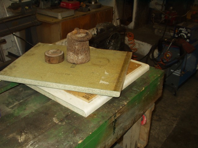
When considering materials for the stator I contacted many plastic suppliers for specs on various plastic type materials in sheet form 13 mm thick. Almost all have a low melting point and any with good thermal qualities cost an arm and a leg plus I would have to take a full sheet. So for this experimental stator I decided to cast a GRP stator to keep the cost down and if it works out then I will build the next one with Tufnol (pressure laminated paper or cotton in resin) it is very tuff but easy to machine.
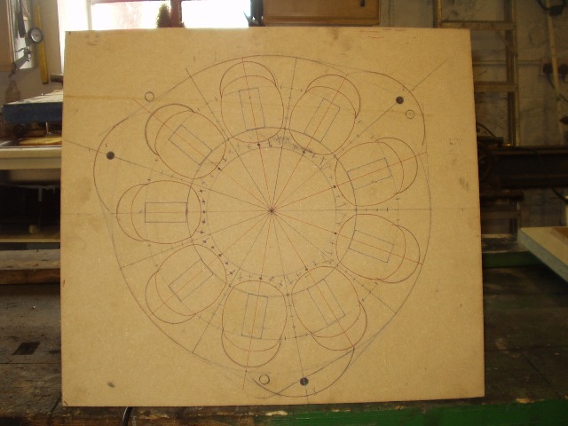
I decided as a first step to draw it out full size on 12mm MDF to use as a ref for templates and jigs for the router and to check that it would all fit. The layout is almost identical to the original Hugh Piggott design but I had to change the position of the mounting holes. The coils are in there original positions but will not be cast in place.
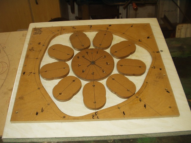
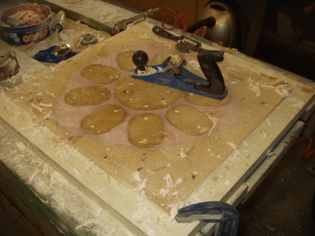
The mould is slightly different to the norm as there is an island for each coil
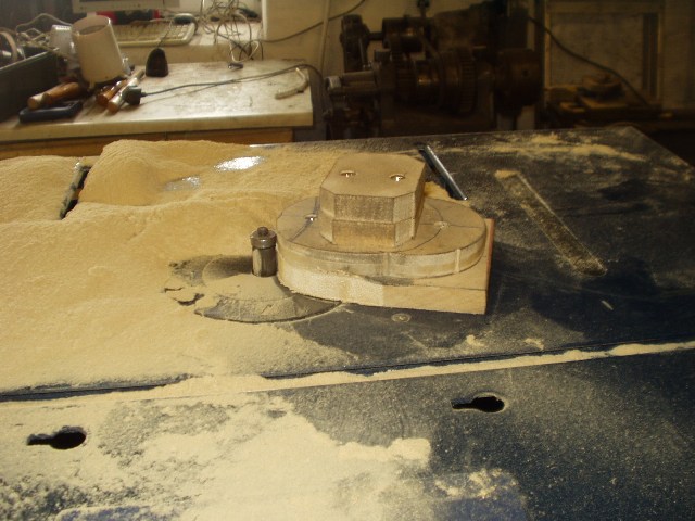
The coil islands where all cut on a router table from a master jig so all where identical
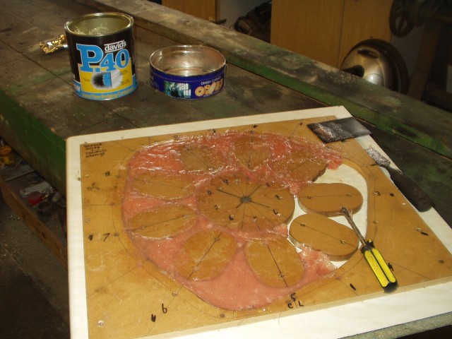
I have problems getting resin and matt locally so for this one I tried "Fibrefill" for those that haven't used it before it is just resin with chopped mat already in it. It is reasonably cheap and easy to get from any car parts shop. I was able to push the mixture well into the mould and vibrate it with a sander to remove any trapped air. This all went very smoothly and without any problems.
I closed up the mould, weighted it down and went for cup of tea.
On my return after about 20 mins the stator had set and I was able to start levelling off the top, this was best achieved with a sharp smoothing plane and belt sander
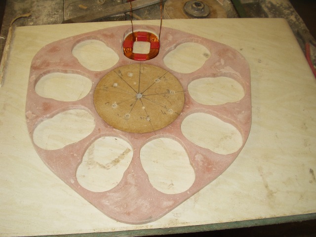
The stator almost fell out of the mould but I left the centre island in for now as a ref datum for centre.
See part 2 for the rest of the story
