Hi Guys just an update on the new stator upgrade.
As a quick reminder this is for a 10ft 48v dual rotor, 3 phase with each coil 150t of 2 in hand 21# all coils have been left exposed to the elements for improved cooling. I also wanted to test a few ideas on this for a larger machine that is still on paper.
Thursday 31st the wind finally dropped enough to allow me to remove the turbine and get it onto the bench and fit the new stator! But it wasn't going to be that simple!
Problem one the bearings in the GM hub were shot !
Problem two you cant replace the bearings in this particular hub, not such a good design
Time for a cold beer a smoke and a bit of a think!
I have a 1996 Renault Laguna 2.2 Diesel that was given to me last year by a neighbour who ran out of road after a few to many beers

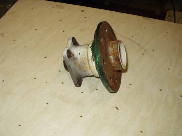
I had a quick look and was delighted to see that Renault use a similar type hub and spindle to the GM type but there was a snag, they don't use a drive flange as such , the brake drum is the flange. Fifteen minutes later and both swinging arms were cut and the whole lot was on the bench.
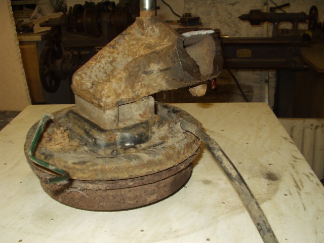
At this point my thoughts are to cut the brake drums down to size to form a flange and then I thought to myself why bother, just let the drum run as a flange, save a bit of time and effort. I then had another flash of inspiration which called for another beer! Why not leave the brake shoes and backing plate in place as a mechanical brake for shutting down it could be applied by hydraulics or by the handbrake cable. The only snag I could foresee was it might push the position of the blades to far forward but after a few measurements and sizing up I could see it would only move them forward by 2 inches.
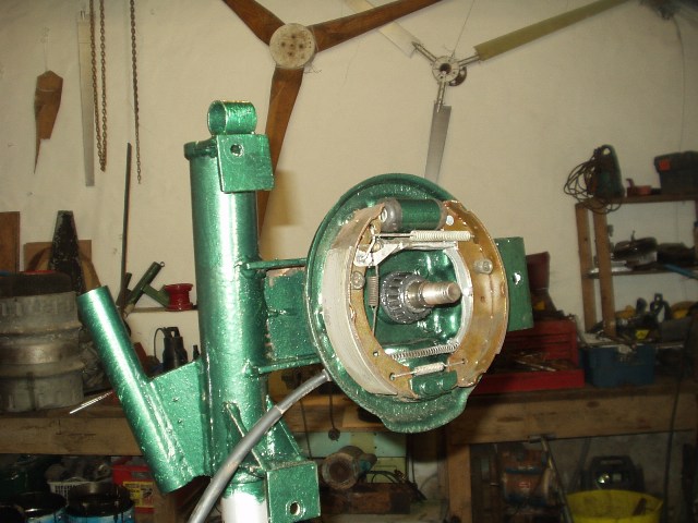
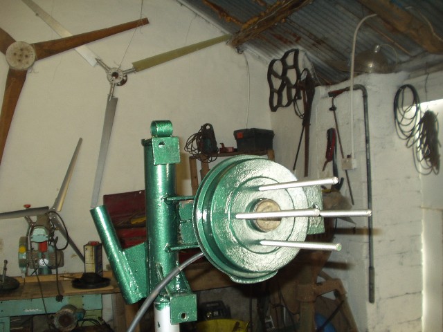
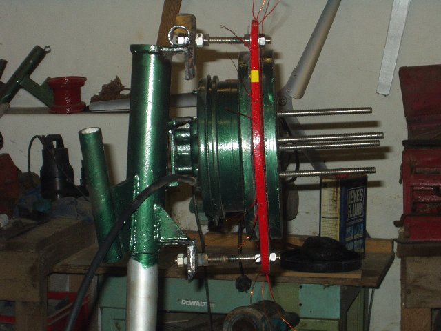
I also wanted to increase the offset on this machine from 5 to 6 inches so that was achieved at the same time. Very little modification was needed to mount the new hub, I simply welded a 6 x 4 piece of 3/8 plate into the original mount, I was even able to use the mounting bolts from the Renault. The position of the 4 wheel studs were exactly the same as the GM hub so I only had to tap them out to 12mm x1.25 for the stainless rod. I cleaned and painted the back plate and drum to try and deter rust and then assembled it all on a stand. One other slight mod I made to the brakes was to lock the auto adjuster as I want plenty of clearance and no drag. The other nice thing with this hub is that the bearings are easy to replace and pack with grease.
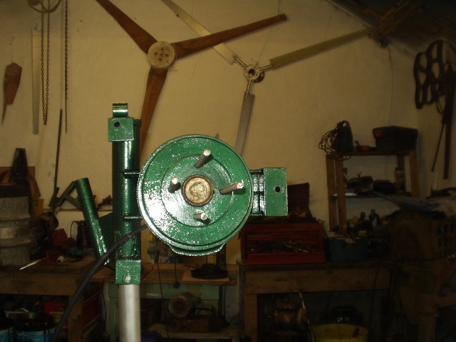
Now for the stator, talk about getting way laid I only intended to change the stator!
On with the fun! I knew I would have to reposition the stator mounts as I had to change the mounting positions from the original Hugh Piggott design plus the change in offset meant it had to be reconfigured. It was a little bit tricky getting it set up to be centred and in the same plane as the rotors but another beer and smoke seemed to help!
All that was left to do was wire up the stator and fit it on the tower. I also needed to run another cable to the tower as this is now 3 phase with the rectifiers at the controller. I don't use slip rings on the tower, I use welding 25mm sq the good quality stuff with the thick rubber outer and the really fine strands of copper, they are secured to the top of the Yaw bearing and pass down through the mounting pole about 17 feet where they get secured to the tower but leaving a bit of slack. The cables can twist around themselves about 15-20 times which is like winding up an elastic band and the theory is that this forces the machine to unwind. I have used this system for about 3 years and have never found them twisted yet. I don't fancy slip rings as I think they are far to risky for this application and are bound to fail at some stage either through wear or corrosion but hey each to their own.
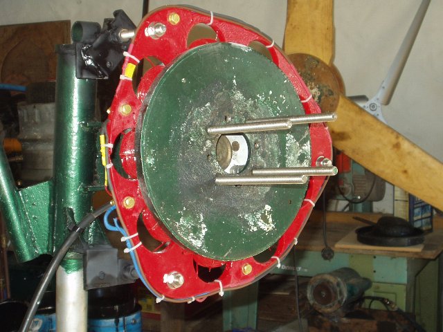
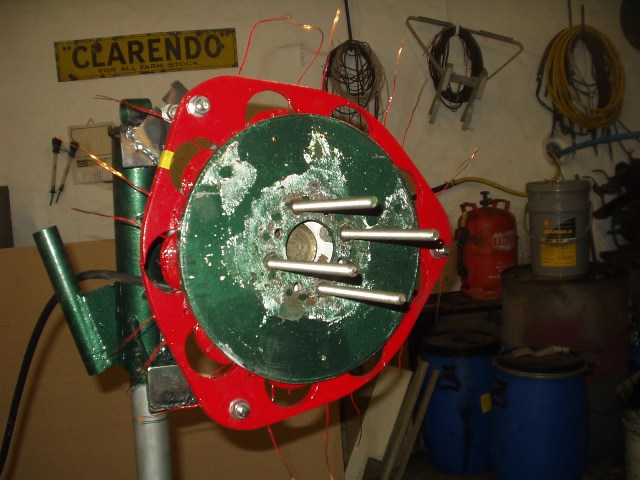
This is the Stator finished and ready to fit
Saturday 2nd I fitted the turbine back onto the tower today with a 15-20 mph wind to make it a bit more exciting lol. I was glad of the brake while I was working on it. My old JCB back hoe has finally died (awaiting an engine transplant) so I was unable to tilt the tower down but as it is telescopic I was able to at least lower it to 30ft. It doesn't sound to high but I have a partial disability with a bone disease in my spine and joints and humping heavy lumps of metal up 30 ft in the air just wasn't going to happen. But with the aid of a block and tackle the mission was eventually accomplished. As soon as I released the brake she spun up and started to produce power.
Its too early to tell how good or bad it is but early indications are good. The turbine is now running slower and a lot quieter than before, at 15mph its producing about 750w of coarse as soon as it was raised the wind started to drop but output has continued and is averaging about 10 amps. I will have to wait for some high winds to see if it is furling correctly but at least I can apply the brake if it all goes wrong!
I would like to monitor the stator temperature and would like to fit a sensor into one of the coils. I have an Oregon Scientific WMR928 wireless weather station it has some spare channels, so I would like to add an extra temp sensor on the turbine to monitor the stator! Has anyone tried this? It is solar powered but would it work within the magnetic circuit?
So that's that job done and dusted, time for a new project!
Russell
