Hi everybody,
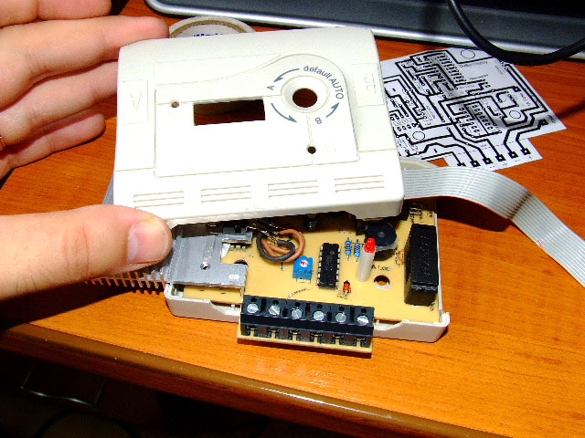
My previous diary entry (which can be found here: http://www.fieldlines.com/story/2007/4/21/194925/365) presented my first solar controller. Now, I'm a visual guy (designer) and I got bored by the bulky case I used then. I wanted a smaller one, with a little more style to it. I started searching for a better box and one day I found this old printer switch and in a second I could imagined my next controller.
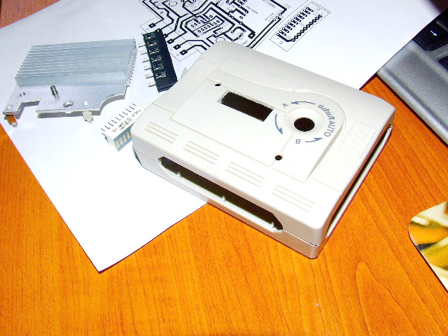
I had to make the PCB much smaller and I had to follow the shape of the previous switch board in order to fit in (lots of holes, etc) The original switch had 2 3mm Leds and a push-on - push-off switch. Perfect! My controller needed just that! So I had to keep those in the same position on the new board so that it could fit to the case front holes while having the tracks built around them (thats much harder than you think).
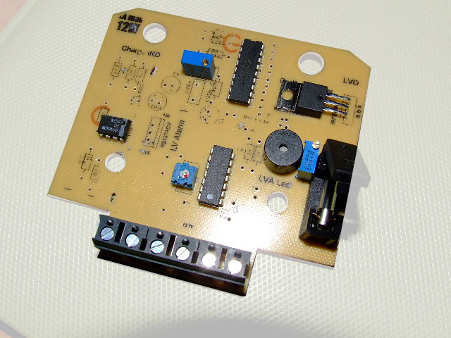
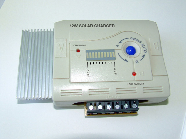
The controller features a 13.8 voltage regulator (PVB137) with a large heatsink, a charge indicator (opamp-driven LED that turns on when charging current > 5mA), a LED voltmeter (LM3914) a low voltage alarm (http://www.aaroncake.net/circuits/lowvolt.asp) with a buzzer and a Low Voltage Disconnect feature that turns off the load when the battery gets down to 11.8V. (thanks Glen). The Heatsink is oversized to keep the PVB cool thus enabling it to regulate up to 1.5A of current but also for a better look (I told you Im a visual guy) On this second version I added a charge indicator LED just to see what the electronics are doing.
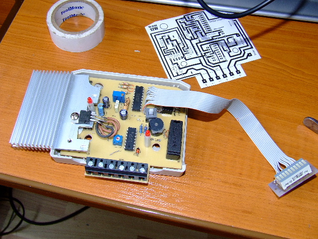
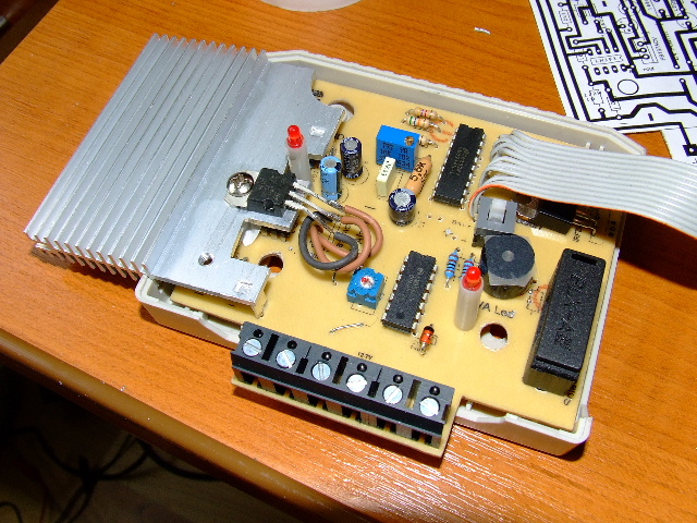
A lot of parts used in making this controller was salvaged from old computers/power supplies, etc. The heatsink too, and I had to make several cuttings to make it fit. But it turned out perfect!
After setting the voltages with a precise power supply I finished the whole thing. I won't bore you with the details of how a begginner like me blew up some parts in the process, spent days to figure out why it isn't working, etc, etc. (thanks again Glen for bearing with me)
I closed the box, glued the LED bar on the front panel and tested the whole thing. Yes, it worked beautifully! The circuit takes 18mA with the voltmeter ON and 6mA with the voltmeter turned OFF (that blue push-button sure came in handy) The charging indicator is very precise, the voltmeter too. I had to use some adhesive tape over that small buzzer to make the sound bearable. I tried several resistors but it was either too loud or too faint. Tape was the best option.
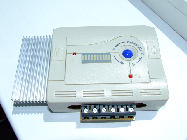
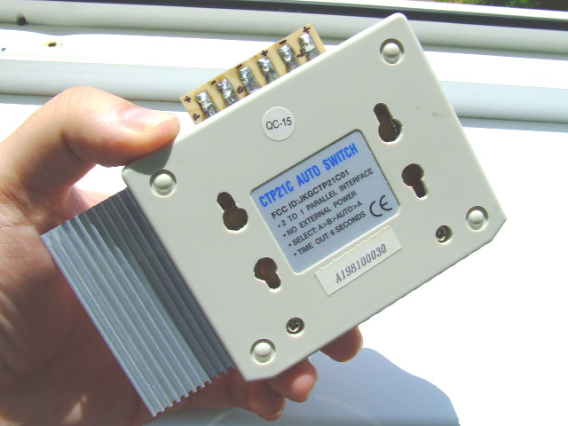
I also cut some keyhole-shaped holed on the back for installing the controller on a wall. The external connectors below are the Panel/Battery/Load pairs.
And here's how it will all look like when I'll be ready with printing the front panel:
This is merely a toy compared with the commercial solar controllers. But it's tailored to my needs right now as my solar panels are << 5W. All its features came from several circuits I found on the net. But I could not have done this without help from my friends. So I have to thank them for making all this possible.
