Hello guys,
After my last series of Vawt failures, I thought I had to at least try and redeem myself. So I kept working at it and finally got what I believe is some good success with the simple SAVONIUS VAWT rotor. I am very excited about it--I think there is alot of potential with the Savonius Vawt. I did many, many different things attempting to do the Darrius type vawt, but this complex type always only went upto around 30rpm max. with no real torque.(It wouldn't self take-off into lift) So I decided to go for the TORQUE and not the speed.
I decided on the simple SAVONIUS type to capture very low wind and breezes in turbulant areas, hoping to get at least 2-30 watts of nice CONSISTENT low power for most of the day. (primarily in the summertime--when wind is almost non-existent)
The following is just a simple PROTOTYPE of the Savonius vawt rotor. It has hard maple wood arms and pine blades. When I get settled on a good powerful design , I will make the arms out of hardened 3/8" think steel and make the whole thing as strong as a tank!
And I will custom make the very slow RPM alternator for this Savonius rotor. (cut-in probably around 40-60 rpm)
I will ask for help with coils at that time. (soon) Here is my advancement so far:
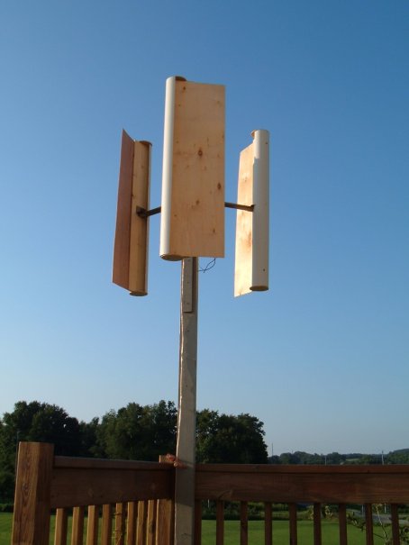
I must say I love the look of these VAWTs. The dimensions of this prototype are 34" total diameter and 39" high. The blades are about 14" wide. This prototype has been turning ALL DAY in a turbulant (stop and go breezes) corner of my house at ground level. It turns 60rpm in the smallest breeze and with pretty good torque.
VAWTMAN was right, these things turn mega easy! I just needed much WIDER blades!!!
I can't wait to test this thing in a real wind! (20mph+)
The front 'nose' part of the blades are simply 4" pvc plastic drain pipe. (the thin kind) I cut it in half with my table saw. A jigsaw works also.
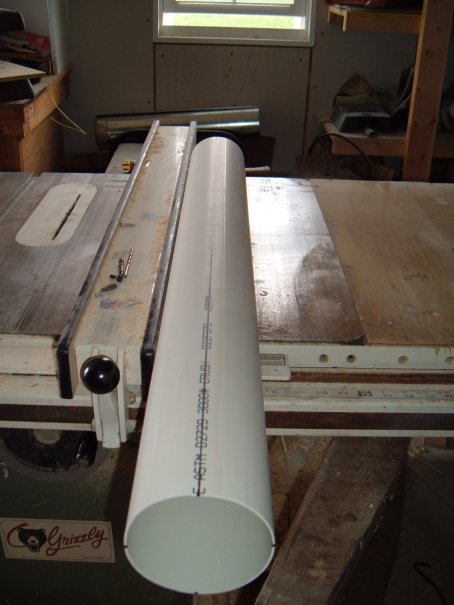
This big 4" 'nose' is held on with only a couple of screws right now, but I found out that there is quit a boost in rpm with putting a 3/8" nut between the nose and the wood of the blade so that the wind pressure will go all the way around the INSIDE of the 4" PVC nose. So now there is a 3/8" airgap for the wind to flow around on the inside. Difficult to explain. Here is a simple picture if you can see it.
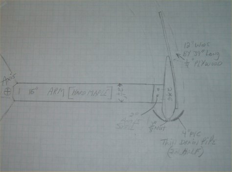
Obviously, the wind is driven up BOTH sides of each blade in its PVC nose to keep pushing it forward. I also put 4" round (1/4" plywood) end caps on the top and bottom of the blades for better pressure. They did help.
So I am learning some good principles now about these type rotors and after examining Windstuff ED's nice Lenz2 savonius mill. Very interesting! I am still experimenting though to narrow down an even better design than this prototype with possibly an airfoil shape on the outside of the 12 to 14" blades, to hopefully get alittle more lift like ED's.
For braking in high winds, I am going to simply have each blade on an axis at the end of each arm so that during a very strong gust, centrifagal force pulls the blade outward (resistant spring) and slows it down like an airbrake. Its actually quite simple. I'm also thinking about using 1/8" plexyglass instead of the 1/4" plywood. It would look much less noticable. Or I might use thin galvanized sheet metel blades wrapped around a wood frame similar to ED's.
It has been and will continue to be ALOT of fun doing this. I would appreciate any and all comments and suggestions concerning anything to do with this!!!
If you have any questions-- just ask man.
