Trailer Mounted Solar Concentrator / Tracker Array
=============
BACKGROUND
I have finally collected and accumulated the parts to build some serious solar concentrators.
Up front -- yes, yes, and yes, I am fully familiar with trough collectors, multi-junction PV concentrators, and how conventional pole and rack mounted single dimension (or two dimension) trackers work Instead my goal was to "low tech" the basic design to the point that anyone with an 8th grade or so education could copy this with parts easily available in most any rural area from materials that are mostly salvage, quick and cheap to repair or replace, and not worth stealing - as contrasted with Aluminum frames, PV arrays, or exposed copper.
After poking at this for a year or so, I now have TONS flat mirror (yeah, really, literally tons of scrap mirror laying about) that I have gotten for little to no cost and is otherwise trash, along with steel frames and other equipment needed to build a set of fully function sets of test equipment.
============
THE WHY:
The highly portable aspect (trailer mounted) of this design is to give it the potential to be a profitable business adventure for me.  As any successful "bidness" folks know, you can run a charity as a business, but you cannot run a business as a charity.  While just one of these fully built will give our household all the power and heat we need for our house and shop, I am thinking there should be a market in putting these out at customer sites.
Presently our major electric utility supplier is gouging the snot the out the consumers in the major electric markets here (Texas).    However, if a would-be renewable energy (RE) producer wishes to operate from a fixed site, and place power upstream onto the grid, you get very little for the power you send up, but whoever buys it back off the grid from the utility gets hammered.
To get around that utility corporate model, I had looked at doing local distributed generation from local sites where power could be shared with multiple commercial neighbors, however, as that involves fixed capital costs for the underground ducts, wire, transformers, and comes under the domain of building codes it is much more expensive and slower to implement than mobile equipment.
By going fully portable to a customer site all the cost and loss of power transmission (the high voltage power towers and transformers) the cost and loss of distribution (the poles, wire and meter part) and administrative costs and CEO stock options are all avoided.
My present thinking is to place the RE generator on the customer site, and do not make them buy hardware (like PV arrays, inverters, batteries and all the rest of the mess), as these are business people - not techies or nerds like us -- and just let them buy electric power being generated at their site for half the price of the big utility.  After visiting with a few potential customers it looks like a serious "GO."
Additionally, there are aspects of property taxes - vehicles and trailers are not fixed property -- that this may avoid, as well as service to the units can be done in shop conditions rather than the field by towing a new mobile RE generator to the customer site, swapping the plug connection, and driving home with the one to be serviced behind the truck.
=
============
THE HOW:
I have details of the intended trailer mounted array and tracking below. I have left the heat collector portion off the diagrams for simplicity, but will cover it in a separate diary entry, as well as the control system, turbine, and motor/generator.
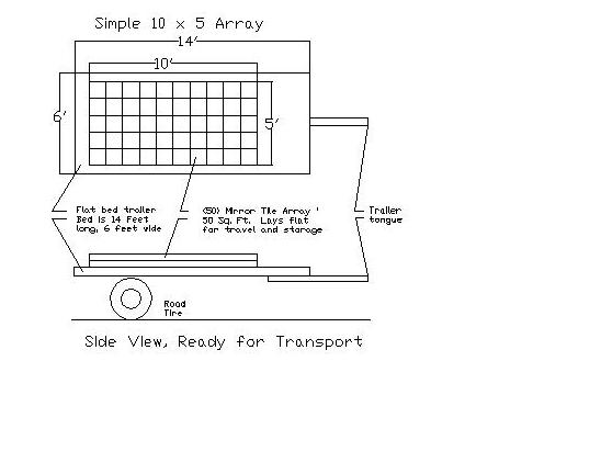
The first round of this should be very simple, it is basically spec'ed in Step 1, below, and shown in the first picture, and it is only 50 mirror tiles totaling 50 square feet - about the same as an 8 foot dish. These all focus onto a one foot square target. While I know this will work, it is not getting the most use of the equipment.
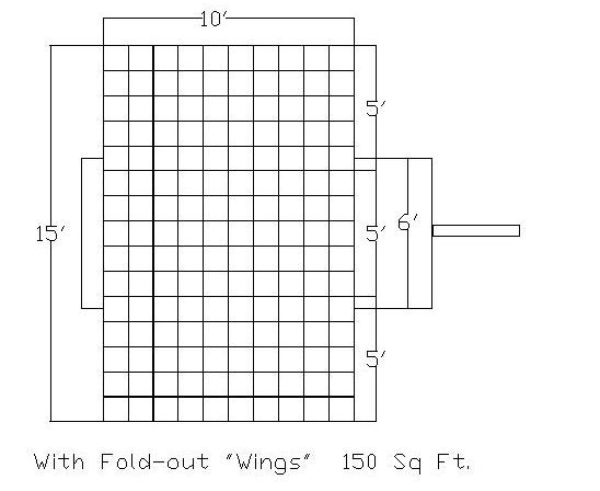
The second step (Step 2, below) gets a little more complex mechanically. It has wings that fold in to stay within the trailer boundaries, and within the legal width limits for highway travel. As there are now 150 mirrors focused on the same 1 foot square target, the heat will be much more intense.
On the back of these wings will be a hardcover to make the whole device hail and severe weather resistant when folded down - typical night time or severe weather (no sunshine, anyway) storage.
On the third step, (Step 3, below) I add another 5 feet to the top of the array bring the total area to 225 square feet and giving a multiplier effect of around "200 Suns." The trade-offs is in how quickly the heat can be drawn away and put to work. If I cannot pull this much concentrated heat away quickly enough, larger individual mirrors are in order for larger arrays. (see mirror options on step 4)
By the time I get to the fourth step, I will be using a larger trailer, with 8 feet width for highway travel, and 8 feet wide wings. The lifting frame will be salvaged commercial steel roof trusses, and the underlying trailer will be 20 long ones we use for carrying bulk steel and pipe.
I suppose it should be noted that this rack and tracking mechanism is also suitable for PV and is probably rather cost effective when compared to the large bore hole, pipe and concrete foundation systems I have seen installed. It also appears to have a longer daytime tracking travel, and would not have to be adjusted seasonally, as do the one dimension tracking arrays.
Other potential improvements include making it drop-on/drop off from the trailer with a pivot bearing on the ground at a customer site.
=
=============
DETAILS NEEDING RESOLUTION AND SUGGESTIONS
Here are some of the details that I am still pondering through:
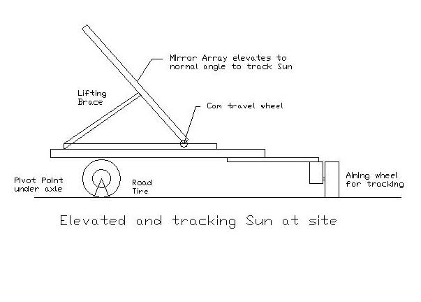
"Best" lifting mechanism - a couple come to mind that I have lying about the shop:
- A garage door opener style gear and chain drive, or
- A cable and motorized hoist, or
- A long screw jack
Does anyone have any other good ideas in this domain, or anyone see anything bad in any of those? I also think I should add some sort of speed brake to slow the descent if the lift mechanism were to somehow fail.
Wind load management - while it will clearly be live tested to withstand a 70 mph headwind (going down the highway as a trailer), that will be only while it is fully folded down. As far wind loads directly on the open array -- as the array is always in line with the length of the trailer making it unlikely that a straight wind could topple it, but it would place quite a wind load on the lift mechanism.
To guard against side gusts toppling the equipment it may be advisable to hard anchor the pivot mount under the axle and tie the whole system down through that pivot joint. I am thinking that a wind speed anemometer may be also be advisable, and to have the whole device lay down and fold up if the local winds get too high.
Weatherproofing the mirrors - This is a vital area, and where prior art similar devices tend to eventually fail. What does anyone think about painting the backs with epoxy based paint? And sealing the edges with silicone?
Anything else that is obvious that I have missed come to mind?
============
Step 1: (See figure 1, below)
Array Size 50 square feet, 5 X 10 feet
Mirrors: (50) 12 inch X 12 inch
Array and Equipment Weight: 150 to 200 pounds
Trailer Size: single axle, 14 feet long, 6 feet wide
:Step 2: (See figure 3, below)
Array Size 150 square feet, 15 X 10 feet
Mirrors: (150) 12 inch X 12 inch
Array and Equipment Weight: 450 to 600 pounds
Trailer Size: single axle, 14 feet long, 6 feet wide
Step 3: (no picture)
Array Size 225 square feet, 15 X 15 feet
Mirrors: (225) 12 inch X 12 inch
Array and Equipment Weight: 700 to 900 pounds
Trailer Size: single axle, 14 feet long, 6 feet wide
Step 4: (no picture)
Array Size 576 square feet, 24 X 24 feet
Mirrors: (96) 36 inch X 24 inch to
(192) 18 inch X 24 inch (depends on desired amplification)
Array and Equipment Weight: about 3000 lbs.
Trailer Size: dual axle, 20 feet long, 8 feet wide
=============
FIGURE 1: First (Small) Test Rig, folded down for travel
==============
FIGURE 2:  Elevated at site.


==============
FIGURE 3:  Expanded with fold-out wings.