I have to start this diary entry with a thank you to ScottAI who was my "Yoda" in
learning a little about op amps and who is truly the architect of this circuit... but anything messed or in error in implementing this circuit is my doing, not his.
I have built a tiny bread board to test the op amp's voltage comparison and switching. (Picture.) It works. The rest of this circuit is just "more stuff" around the core.
One goal was to make a single dump controller that could be used for 12, 24, and 48 volts systems. 48 volts systems add a little challenge since many parts aren't rated to voltages that high. To overcome that, an optional pre-regulator is used to to lower the input voltage to around 30 volts where the primary voltage regular can regulate the voltage to the 9 volts that the circuit operates at. The pre-regulator is not needed for 24 volts systems and should not be installed in 12v system. Given that, depending on whether the pre-regulator is installed or not, the circuit can be switch between 48v and 24v or between 24v and 12v with a single jumper. This feature is important to me because I, depending on the season, switch my battery voltages from 12v to 24v. (Using 12v wiring and small 300 w inverter, I still get enough power to run my shop lights in the summer when we have very little wind. Otherwise, I wire for 24v and have a 1800 w inverter for use in winter and spring.)
Another goal was temperature compensation. We'll typically see 0F in the winter here and 90F or so in the Summer. Day to night temperatures typically differ by 20F to 40F; seems like the circuit can adjust itself for that without my help.
The circuit is not a charge controller. It does provide temperature compensated voltage selection of a charge voltage, a float voltage and an equalization voltage. I'm not that sure about the value of temperature compensated equalization voltage as my understanding is that the battery heats up during the process. However, I think it's okay as the controller should lower the temperature if the battery overheats...
The last goal was to make the circuit interface electrically to a charge controller. The notion is that the charge controller will switch the dump controller between charge and float modes depending on the charge controllers determination of whether the battery needs charging or not. In the absence of a charge controller, an on-off-on switch can be used to select charge, float or equalization under manual control.
The schematic is just a little bit larger than the rules for posting so here's a link to it -
http://www.otherpower.com/images/scimages/6527/tiny17s.gif
Depending on the choice of MOSFETs and heat sinking, the circuit should handle about 50 amps of load. As with other circuits along this line, the cap on the positive input of the op amp (C4), the size of the load and the battery capacity will determine the period of the switching. The target is about 300Hz under load. Large loads may take several 10's of uF so room is left on the circuit board at C4 for using larger capacitors.
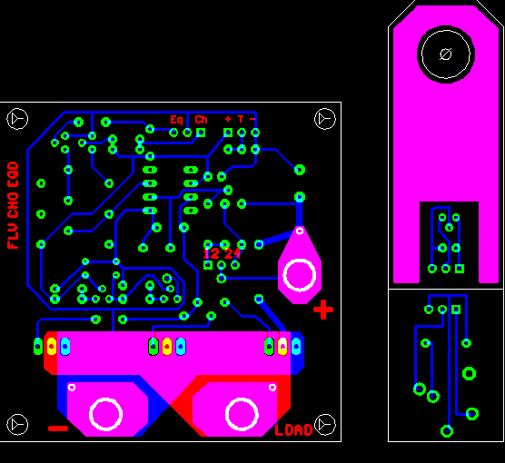
The control area is a one sided a layout.

I've had pretty good luck with the high current plains on two layers as shown and it's not too difficult to make that part of the circuit two sided since, if you miss, you only have a little bit of trimming around the FET pins to do. One ounce copper is good to about 30 amps, add some copper wire to the drain and ground plains to get up to 50 amps.
The large circles are holes to drill for #10 screws and act as the high current terminals.
The mini boards on the right are for the temperature probe (upper) and receptacle for the temperature probe (lower.) Since I'm not that good at making nice boxes, I'm considering making the board a little larger and putting the miniplug receptacle and a modular phone connector for remote control directly on the main board.
The idea of the temperature probe board is that the hole at the top will allow it to go onto the screw on the plus battery terminal. The copper will conduct the heat to the temperature sensor, IC5. IC5 is a TO-92 package and should be bent over and glued onto the copper. Then the circuit area and wiring should be coated in plastic dip or equivalent to insulate it and protect it from the elements.
The voltage comparisons on the main circuit are biased with the .6 volt at 0C voltage offset of the LM61 temperature sensor. If the sensor is unplugged, R14 (on the lower mini board) will switch in and provide the equivalent offset of a 17C temperature.
The the main board layout is "modular" in that if you want to mount the FETs separately you can just cut the board above the FETs. (Then it truly is a one sided board.) Or you can cut, rotate and paste another FET area on the bottom side of the board, run a jumper across the drain or ground plain and have six on board FETs. Not sure about the drive capacity of the op amp in that case so you'd definitely want to pick FETs with low input capacitance.
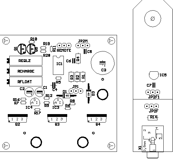
Here's a placement to show where the parts are -

Currently, the main board is about 2.5" square.
I'll be a few weeks before I'm able to build this board so all comment pre-build are especially welcome!
Thank you very much,
- Ed.