Author Topic: Got PWM.  (Read 4046 times)

0 Members and 1 Guest are viewing this topic.

bigkahoonaa

  • Jr. Member
  • **
  • Posts: 57
Got PWM.
« on: October 13, 2007, 05:28:24 AM »
Recap: I built a Hugh Piggott 8' wind mill, but instead of using 80 turns per coil, I used 800 terns.  Bad idea!   I magnified everything by a factor of 10.  Instead of seeing blade stall at about 300 RPM, I was seeing blade stall at 30 when connecting a 12 V battery.  Mill AC volts could pulse from 4 to 8 to 12 to 14 VAC and drop to 4 VAC every second or two.  I thing oztules summarised it best:


acceleration without load up to 12v or so, then the battery and rectifier kick in and swamp the blades making them stall and decelerate.... then with no load again, they speed up... only to get kicked in the head again by the battery.


I'm trying to add PWM to balance aerodynamics with battery charging.  Here's a pic of my circuit:


Some block connectors are missing and the PWM circuit was modified.  This is a circuit diagram:


I feel this is not an optimum design.  Some posts on this site suggest that:


  1.     You should avoid anything between rectifier and battery.  Any PWM on the AC side of the rectifier would need twice the MOSFET, messy.
  2.     It's a bad idea to put heat generating components on a proto board.  It will melt.
  3.     The proto board can't take high amps.
  4.     You're playing with ground, and that's a "no-no".  I  don't have a p-channel MOSFET.


I'm trying to get my software to balance TSR, RPM, duty and baterry chatge.


Mau

« Last Edit: October 13, 2007, 05:28:24 AM by (unknown) »

Flux

  • Super Hero Member Plus
  • *******
  • Posts: 6275
Re: Got PWM.
« Reply #1 on: October 13, 2007, 12:47:40 AM »
Good luck


With that number of turns on your alternator and that circuit you will need it.


Flux

« Last Edit: October 13, 2007, 12:47:40 AM by Flux »

commanda

  • Hero Member
  • *****
  • Posts: 731
Re: Got PWM.
« Reply #2 on: October 13, 2007, 01:47:00 AM »
Have you considered just using a transformer (or 3)?


And I strongly disagree with 4 in this particular application.


5. proto boards have too much stray capacitance for this application.


Amanda

« Last Edit: October 13, 2007, 01:47:00 AM by commanda »

tecker

  • SuperHero Member
  • ******
  • Posts: 2183
Re: Got PWM.
« Reply #3 on: October 13, 2007, 07:42:23 AM »
This will digress a little from your circuit design but the only way to keep your rpm up that is practical is to match your Voltage at a good working rpm with batteries . Then you can time your pulse width way out there without effecting your stator regardless of how dense the stator is .Four or five old car batteries and your in the house. I doesn't matter if these front end bats get a full charge all the time just set the mean charge time to keep them up. Then you only have to protect against runaway on the electromechanical side (field side).  
« Last Edit: October 13, 2007, 07:42:23 AM by tecker »

kurt

  • Hero Member
  • *****
  • Posts: 925
  • Country: us
    • website
Re: Got PWM.
« Reply #4 on: October 13, 2007, 05:31:41 PM »
your best bet would be to spend the bucks and build a new stator according to the plans be sure to use the correct size wire and correct number of turns and correct number of coils and all that do it right it will work great. i think continuing with this current stator is going to be an exersize in pointlessness and you will end up getting no ware.
« Last Edit: October 13, 2007, 05:31:41 PM by kurt »

oztules

  • Hero Member
  • *****
  • Posts: 1477
  • Country: aq
  • Village idiot
Re: Got PWM.
« Reply #5 on: October 14, 2007, 01:39:57 AM »
Well Bigkahoona,

 As you are aware, I support Kurt on this one that a new stator is in order....... however, I see a stubborn streak here, and it is a bit like me when I have got a bone to chew on.


If you insist on using that stator, I can only offer this way out. (I have dabbled in higher power pwm, and it is a long learning curve for me.... still a long way to go and failure is always close at hand). So for a very reliable PWM, use xt power supplies. A quick 45min rewire will produce a free (I assume you will get the psu 's from XT's for free for sure), 150-200w unit which you have complete control over.

For 5 phase with your existing relay switching arrangement on your desk you can switch in or out as many as you wish... use the inhibit pin on the tl494 for this function. You can switch between 110v and 240v on each supply (switch is on the back and you can use your multitude of computer controlled relays to make or break the contact)), you can establish whatever current per psu you want (between 0-15A), and can set the upper voltage to whatever you please <16v preferably)


It will require about 45mins work per unit, and it will be stable, controllable, and in your setup, the cheapest to fiddle with for the best results. I guess you could hook your computer up to a wind speed indicator and have a mppt system too.) A bank of 10 of these would give you a varied load for the mill at high impedance.... if you wanted to get creative you could set the currents differently on them all and switch them in sequentually.


At the risk of hijacking your thread, here is one in operation. This one is driving a 12v coffe maker at moderate load 8v@10A... the trimpot sets A max.


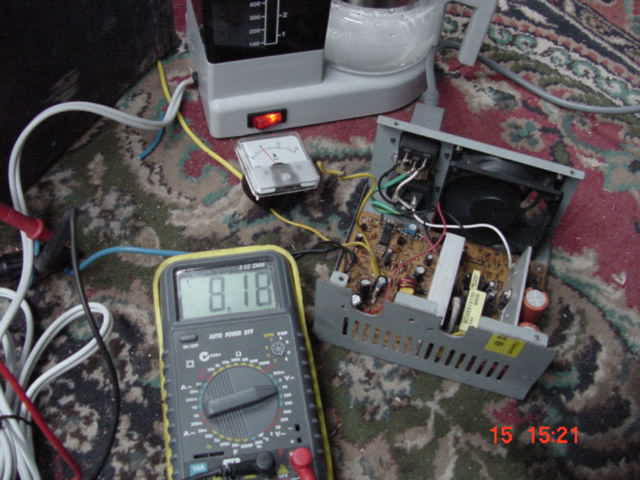
By turning the trimpot up in this picture, we control the output current, the voltage rises until the new max current is drawn by the load.


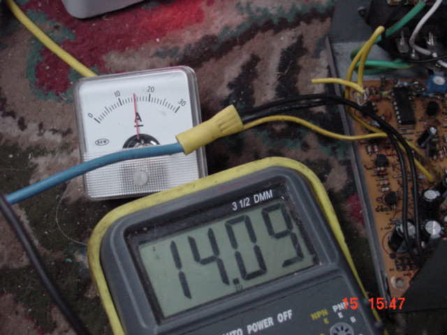
Here it is turned up to 15A, the voltage has risen to a point where 15A is absorbed by the load (coffee maker)  and the voltage happens to be 14v You can set the voltage hardwired (as I have at 14.5,) or the current...or both which ever value reaches it's max first controls the output... ie if I turn up the amps even more, only a small current change would occur as 14.5v voltage limit (I have set by fixed resistor) would then limit the output, not the curent any more.


Now as your lower power winds are in operation you can turn on /off different psu's set at different current levels (if you wish to utilise that huge array of relay drivers on your desk), simply connect to pin4 of tl494 to turn on the supplies, this means no heavy dc switching in the relays only a few milliamps


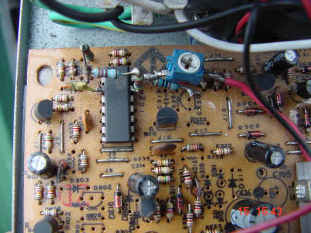
So using 4 resistors, a trim pot a small capacitor a piece of wire (for the current sense 2"long) and a pair of side cutters you can achieve what you want.


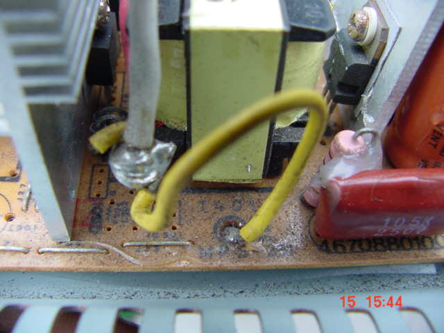
oh and here is the current sense


It would be compact, reliable controllable and scalable.... and basically free..... pretty messy I admit too )


Personally I'd build a new stator, but a next to free solution is available to you.... only take a lot of desk space and your time..... I figure this will be a whole lot faster than designing a multi kilowatt design from scratch.


Plenty of silly ideas left to play with over here..

Guess you could tell that though..


.........oztules


.

« Last Edit: October 14, 2007, 01:39:57 AM by oztules »
Flinders Island Australia

bigkahoonaa

  • Jr. Member
  • **
  • Posts: 57
Re: Got PWM.
« Reply #6 on: October 14, 2007, 10:07:41 PM »
Amanda:


That was my ideal, try do use 120 VAC transformers to get 12 VDC for battery changing.  I underestimated a battery's abiliy to limit RPM.

« Last Edit: October 14, 2007, 10:07:41 PM by bigkahoonaa »

RP

  • Hero Member
  • *****
  • Posts: 722
  • A dog with novelty teeth. What could go wrong?
Re: Got PWM.
« Reply #7 on: October 14, 2007, 10:15:50 PM »
I'm afraid with the enormous resistance of your coils, even a dead short won't be able to hold back your mill.


One thing that "might" help (but I'm not hopeful) would be to do some surgery on the stator and rewire the coils of each phase in parallel instead of series.  That would get the mismatch down to 3X instead of the 10X you have now.

« Last Edit: October 14, 2007, 10:15:50 PM by RP »

bigkahoonaa

  • Jr. Member
  • **
  • Posts: 57
Re: Got PWM.
« Reply #8 on: October 14, 2007, 11:09:12 PM »
Ooops  In my enthusiasm to press POST, I forgot to say that I tested it in winds of 3 to 4 m/s.  At 0% duty, the mill blade was very easy to turn.  I let it go to 68 VAC, about 270 RPM.  No very useful at this setting, since it's not charging.  At 30 to 40% duty, batteries were charging at 60 RPM in pulses of about 25 VDC at 5 KHz.  At 100% duty, AC RMS was pulsing again from 4 to 14 to 4 VAC.


I don't have software for circuits.  I have paint, but it's a pain.  This is a pic of my PWM circuit


« Last Edit: October 14, 2007, 11:09:12 PM by bigkahoonaa »

bigkahoonaa

  • Jr. Member
  • **
  • Posts: 57
Re: Got PWM.
« Reply #9 on: October 14, 2007, 11:32:27 PM »
oztules:


Nice Pics.


Forgive my ignorance, but what is xt?


Mau

« Last Edit: October 14, 2007, 11:32:27 PM by bigkahoonaa »

Flux

  • Super Hero Member Plus
  • *******
  • Posts: 6275
Re: Got PWM.
« Reply #10 on: October 15, 2007, 01:14:49 AM »
Those things are computer power supplies I think. Direct off line switching and someone has done the basic design work. I don't know anything about them.


If you have used a design where Hugh suggested 80 turns for 12v then I am fairly sure you must be using the 10 coil 5 phase design. That rules out any sensible way of using transformers. As you have messed about I can't be sure that you haven't changed it to 3 phase, in which case you may have an enormous voltage at cut in.


Pwm switching converters will do what you want, but not simple on/off pwm, you need a buck converter with inductors and commutating diodes. Otherwise you need a transformer coupled switching converter with pwm. If you try what you look to have in mind with just a switching mosfet you will end up with a cloud of smoke. Probably you will with any switching converter built like a rats nest on a prototyping board. The layout of a high voltage converter will be very critical.


Unless you have an incredibly long cable run or you want a long project then a new stator seems the best way to go. If you must try the converter then learn about the things first or try to adapt an available device as Oztules suggested.


Flux

« Last Edit: October 15, 2007, 01:14:49 AM by Flux »

oztules

  • Hero Member
  • *****
  • Posts: 1477
  • Country: aq
  • Village idiot
Re: Got PWM.
« Reply #11 on: October 15, 2007, 01:46:24 AM »
Sorry,

The XT computers are all the older style IBM clones that came out before the AT computers. Their power supplies are simpler than the AT supplies which have a 3v output and sleep mode as well. The XT are +- 12v and +- 5v. They are available by the millions I suspect in all the older  IBM clone computers.


If you get hold of any older dos or windows98 type computers, the power supply will be likely XT. The AT ones are fine as well, but a little trickier to fiddle with. It will solve all your problems, but will be a wiring mess when integrated with your relay switching, but will give you pretty fine tuning of your high impedance alternator into a high impedance load... which is what you need to use on that stator.


I cant think of a cheaper,or  easier way to "cook" your own PWM system as stably as this.


I find they are easily in their limits at 10A, and will run fine at 15 if you filter the current sense better than I have. I have driven them at 20A, but the waveform gets messy due to my lack of care with the feedback on the tl494 the power transistors will likely cook... spectacularly.


I use them as down and dirty 12v battery chargers because I can set their parameters precisely. ie exact current limit (smaller sla batteries, or voltage limit (float charging) etc.


They provide full current even at short circuit... (but the fan stops running and they heat up....the fan draws it's power from the output). At short circuit, the TL494 draws it's power from the ripple in the transformer and runs without a problem at short circuit. They are pretty bullet proof and haven't had one fail in the last 4 years.... and do some dreadful things to them.


They look like this in their native form (before you butcher them):


Have fun


.........oztules

« Last Edit: October 15, 2007, 01:46:24 AM by oztules »
Flinders Island Australia

bigkahoonaa

  • Jr. Member
  • **
  • Posts: 57
Re: Got PWM.
« Reply #12 on: October 16, 2007, 10:12:49 PM »
You've got some 'splaining to do, Lucy:


I don't think I expressed myself very well in this post.  I'm not trying to build a high volt/high amp battery charger.  That's way beyond my capabilities.  I'm trying to use PWM to adjust aerodynamics and loads in winds of up to about 5 m/s, low wind days when the genny is not producing massive amounts of power.  I get more low wind days in the summer. I'm thinking of something like a float charge.


I tried to build a separate PWM switch, but it didn't work.  That's' why the PWM circuit's on the proto board.  I can see commanda's point.  Proto boards have too much stray capacitance.  There's no solder between joints, so you get a tiny gap between metals and a very small capacitor.  It shouldn't be a problem with DC volts, but it can build up in an AC circuit with many joints.


Mau

« Last Edit: October 16, 2007, 10:12:49 PM by bigkahoonaa »

oztules

  • Hero Member
  • *****
  • Posts: 1477
  • Country: aq
  • Village idiot
Re: Got PWM.
« Reply #13 on: October 17, 2007, 02:54:13 AM »
In that case, a single one of the xt power supplies will be sufficient to give you accurate float voltage at the current you set. It will give you the high impedance you need directly on the dc output of your mill to stop the hunting.


The poor transfer at lower input voltages will likely give you some slack in the current dept. It's a cheap starting point. The ability to control the output current will allow you to set it to whatever you find is a sweet spot in your fluky winds. It is very flexible... and the tricky power electronics are done for you.... and it isolates you from the high voltage dc.


However, you may have to use your relays to take care of runaway.


.......oztules

« Last Edit: October 17, 2007, 02:54:13 AM by oztules »
Flinders Island Australia

bigkahoonaa

  • Jr. Member
  • **
  • Posts: 57
Re: Got PWM.
« Reply #14 on: October 17, 2007, 07:46:41 AM »
oztules


I took a PC power supply appart once.  Is it just a matter of adjusting the two pots inside?

« Last Edit: October 17, 2007, 07:46:41 AM by bigkahoonaa »

oztules

  • Hero Member
  • *****
  • Posts: 1477
  • Country: aq
  • Village idiot
Re: Got PWM.
« Reply #15 on: October 17, 2007, 12:18:43 PM »
Sadly no.

It requires isolating the two error amps in the tl494 or the dl494 PWM or ka7500 (all the same) chip. (pins 1&2 and pins 15&16). use pins 1,2 as the voltage reference amp, and use pins 15,16 as current reference. The current reference is taken from  the earth leg of the power tranny


A diag of the current sense circuit is here


A discussion I had with another fellow on how to do it on another forum is here... about the eighth post onwards. http://www.austech.info/showthread.php?t=27194

We got success even without pictures or diagrams.


If you still want to go on with it, but that discussion doesn't make sense enough to move forward, we'll perhaps do a diary on converting one from start to finish, as they are very handy and stable powersupplies when set up like this. And this time we'll use pictures as well. (and maybe Dinges will do one too...:)  )


.........oztules

« Last Edit: October 17, 2007, 12:18:43 PM by oztules »
Flinders Island Australia

dinges

  • Hero Member
  • *****
  • Posts: 1294
  • Country: nl
Re: Got PWM.
« Reply #16 on: October 17, 2007, 01:12:13 PM »
...ouch...


You don't forget easily, do you ?


Peter.

« Last Edit: October 17, 2007, 01:12:13 PM by dinges »
“Research is what I'm doing when I don't know what I'm doing.” (W. von Braun)

bigkahoonaa

  • Jr. Member
  • **
  • Posts: 57
Re: Got PWM.
« Reply #17 on: October 17, 2007, 01:40:43 PM »
Guess I'll need to scrounge around for an old power supply.
« Last Edit: October 17, 2007, 01:40:43 PM by bigkahoonaa »

dinges

  • Hero Member
  • *****
  • Posts: 1294
  • Country: nl
Re: Got PWM.
« Reply #18 on: October 17, 2007, 01:49:14 PM »
...mumble mumble... he'll keep harassing me till I do ... mumble... where are those blasted PSUs anyway... mumble... haven't met an Aussie I liked yet... mumble... there it is...


Just remember: if I die in the attempt, my blood will be on your hands.


Peter.

« Last Edit: October 17, 2007, 01:49:14 PM by dinges »
“Research is what I'm doing when I don't know what I'm doing.” (W. von Braun)

BigBreaker

  • Sr. Member
  • ****
  • Posts: 302
Re: Got PWM.
« Reply #19 on: October 17, 2007, 03:09:52 PM »
Be careful with big capacitors.  They REALLY hate to be shorted when charged up.  Best to use a big resistor to discharge them before handling.


I'm a pretty well trained EE and I still managed to make some serious lightning and a drop or two of molten copper with an old XT PSU.

« Last Edit: October 17, 2007, 03:09:52 PM by BigBreaker »

oztules

  • Hero Member
  • *****
  • Posts: 1477
  • Country: aq
  • Village idiot
Re: Got PWM.
« Reply #20 on: October 17, 2007, 04:55:06 PM »
Now that looks like an excellent candidate for conversion Peter.


Just remember, if you vaporise yourself, you will be able to discuss zubbly conversions with the King..... remember to take your phone with you though, as I assume you will be installed in the "down stairs" apartments.


:)


......oztules

« Last Edit: October 17, 2007, 04:55:06 PM by oztules »
Flinders Island Australia