Author Topic: Home-built anemometer project  (Read 7113 times)

0 Members and 1 Guest are viewing this topic.

elt

  • Sr. Member
  • ****
  • Posts: 328
Home-built anemometer project
« on: October 22, 2007, 11:04:17 PM »
I started to build an anemometer so that I can get a better handle on how well my mill is performing.


I bought a cup set from our host and dug out a pair of little servo motors I'd had for some time -


The motor has a 3mm shaft. I ground a little flat on it, drilled the cup hub out to 1/8" and put in a set screw. The motor was just a little smaller than the ID of 3/4" schedule 40 PVC so that looked like a good mount.


I opened one motor, looked up its controller chip and figured out that the back-EMF taco function should work even without the motor being powered... it did but I didn't get "good" readings at low speeds. The control chip claims a "divide by 2" of the commutation speed and a "de-jitterer" ... the taco wire doesn't really give linear pulses until about 200 rpm but it did look like it might be consistent at lower speeds so I moved forward thinking I would work it out in calibration. But outside in the wind though, I didn't get any readings at low speeds. (Inside, the cups turn consistently at walking speed but the taco doesn't give a reading at all.)


Plan B:


I dug under the chip and saw what looked like a three phase motor. I pulled the controller board out and put my meter on two wires. Each phase is about 10 ohms and makes about .1 millivolt RMS at 100 RPM. (That's pretty good power!) I "dead-bugged" a little opamp circuit onto an 8 pin wire wrap socket -


And wired it up to one of my little microcontroller boards.


Yeah! Most of the display is dummied but the 0030r (30 RPM) is a live reading. Also, it reads 12 RPM walking briskly inside. I was counting; it did seem to be taking about 5 seconds to make a rev... I do see why a "de-jitterer" is needed because I do get spurious readings when it's jiggled.


I'll try changing one of the resistor values a little on the theory that when the motor is not making voltage that it will pull one line a little bit away from the other. I'm not sure if that will get rid of the jitter or just move it to a small rpm. I also know how to do it in software so I can do that if I don't find an electrical solution.


Tomorrow I'll calibrate and then get it in the air.


- Ed.

« Last Edit: October 22, 2007, 11:04:17 PM by (unknown) »

Chagrin

  • Full Member
  • ***
  • Posts: 195
Re: Home-built anemometer project
« Reply #1 on: October 22, 2007, 06:42:06 PM »
Mmmm.... "taco function".
« Last Edit: October 22, 2007, 06:42:06 PM by Chagrin »

elt

  • Sr. Member
  • ****
  • Posts: 328
Re: Home-built anemometer project
« Reply #2 on: October 22, 2007, 07:59:19 PM »
> about .1 millivolt RMS at 100 RPM. (That's pretty good power!)


That should read ".1 volt RMS at 100 RPM"


Using formulae from other threads -

.1 (v rms) * 1.414 (for peak volts) * 3 (coils) * 1.7 (for star connection) = .72 volts


Assume, say, 500 rpm, that'd be 3.6 volts. If it was charging at pair of nicads at 2.5 volts then using Flux'es power estimator, multiply 10 ohms by 1.3 for 13 ohms and figure 2.5 volts goes into the battery so 1.1 volts goes in "heat in the coils." 1.1 volts/13 ohms = 85 mA. 85ma (that'll light a LED!) in the battery at 2.5 volts is 200 milliwatts ... Oops, you'll only see about 2/3 of that because of diode losses in rectifier.


I did think of rectifying the little motor and running that into an analog-digital converter on the microprocessor to measure wind speed but I realized before starting that a diode drop would kill any chance for slow speed readings so I the came up with the idea of using the op amp as a voltage comparator to make a nice square wave. I already had a pulse counter programmed from testing the taco output so using the op amp pulse was a plug and play solution!


- Ed.

« Last Edit: October 22, 2007, 07:59:19 PM by elt »

scottsAI

  • Hero Member
  • *****
  • Posts: 884
Re: Home-built anemometer project
« Reply #3 on: October 23, 2007, 01:12:49 PM »
Hello Ed,


The opamp configuration is open loop with balanced input. Any system noise well be amplified at the full gain of the opamp resulting in noisy output. Best to offset the input with a little negative feedback like a 1M ohm, connected to opamp output to neg input should help with the jitter.


The servo motor is much like:

The most common way is to put a magnet on the cups and a reed switch on the base. Count the time per rev, works way down in speed. The accuracy is very high without calibration, walking along the cups should seam like they are stationary to the floor. Most equations I have seen say about 10% loss of wind speed , math is: actual wind speed = measured / 0.9 or measured * 1.111111111


I prefer a coil vs the reed switch. Reed switches are rated for 1 to 10 million activations, doomed to failure. Coil has no such rating, Coils output voltage will change with RPM requiring circuitry like opamp. Strong magnet allows to work down to low RPM


Add a wind vane with a second switch you can get direction. More complicated to get to work.

I do not like the continuous pot for wind direction, seems to fail after couple years or so.


Software solution for jitter. The on time vs off time vs RPM can be compared. Ignore signals out of band. Some finite time will be required to change RPM. No reason to update the display more often than necessary. Slow speeds each pulse may be a good time, once above 1 Hz then average pulses over the one sec before updating the display.


Have fun,

Scott.

« Last Edit: October 23, 2007, 01:12:49 PM by scottsAI »

BigBreaker

  • Sr. Member
  • ****
  • Posts: 302
Re: Home-built anemometer project
« Reply #4 on: October 23, 2007, 02:42:17 PM »
I agree a coil is better.


Another way to dejitter the signal would be to put a diode across the coil leads and let the current circulate a bit in one direction.  The drop over the diode would be plenty to detect.  A small capacitor and resistor network around the diode can do a variety of things from smoothing out noise to creating nice edge / voltage spike once per rev.

« Last Edit: October 23, 2007, 02:42:17 PM by BigBreaker »

elt

  • Sr. Member
  • ****
  • Posts: 328
Re: Home-built anemometer project
« Reply #5 on: October 23, 2007, 04:15:54 PM »
Thanks Scott,


Hope you got your weather station and it's working well...


> offset the input with a little negative feedback


That didn't help with the problem. I think I've miscalled it "jitter" ... certainly when I googled "jitter" I found a lot a discussion about PLLs but not what I'm seeing. I don't think that the circuit is noisy (at least with what I can see with the limited testing I've done.) I get a nice pulse train with as little as .1 Hz and if I stop the cups I get "zero". But if there's a little movement, either from air currents in the house or a little bit of an unsteady hand, then I get "jitter" but, in fact, I think that the cups are moving a little tiny bit and genuine zero crossings (back and forth) are being detected. I think it's mostly my hand that has the jitters!


> Add a wind vane with a second switch you can get direction.


Of course I'll have to get direction, eventually, but that's just in the thinking-about-it stage. Am leaning to an incremental optical encoder (because I have them) and perhaps some kind of absolute position indicator for syncing the direction. Maybe a reed switch and a magnet...


> Slow speeds each pulse may be a good time,


I didn't think of that! I'm already timestamping the input pin changes for "de-jittering" but I was only counting how many pulses I got in a fixed time frame to figure RPM. That gives me pretty poor resolution at low speeds. Once I get a good pulse, I'll queue it (the time stamp) with the others and then every now and then just average the periods stored to in the queue to calculate windspeed.


Thanks again,

- Ed.

« Last Edit: October 23, 2007, 04:15:54 PM by elt »

elt

  • Sr. Member
  • ****
  • Posts: 328
Re: Home-built anemometer project
« Reply #6 on: October 23, 2007, 04:27:40 PM »
Thanks BB,


I'm sorry to say that I've already potted up what I have to weather proof it.


I appreciate your suggestion; however, I'll have to think about that a while to understand it. I wrote a while back that I was "op amp stupid"; I think that with extreme patience on Scott's part I've graduated to "op amp ignorant." One thing I've learned is that if you get a little bit off the beaten path, you have to know the proper terminology to find answers. I googled for ideas but making up keywords like I think I was doing didn't get my anywhere. If you can tell me what the name or concept is for that you're suggestion, I'll certainly go googling again.


Thank you,

- Ed.

« Last Edit: October 23, 2007, 04:27:40 PM by elt »

scottsAI

  • Hero Member
  • *****
  • Posts: 884
Re: Home-built anemometer project
« Reply #7 on: October 23, 2007, 06:13:34 PM »
Hello Ed,


some kind of absolute position indicator

Too complicated. Here goes. Enjoy.


Using a coil and magnet, assume the coil is pointing north. Each time the cups complete a rev, it gets counted. Simple?

Direction vane. No magnet, iron bar to couple the cups magnet to the center shaft which has a coil below it to sense the field. Nothing touching.

How to get direction?

Time the cups rotation. The vanes pulse will be between the first cups pules and the next! The ratio is the direction! Simple.


Have fun,

Scott.

« Last Edit: October 23, 2007, 06:13:34 PM by scottsAI »

elt

  • Sr. Member
  • ****
  • Posts: 328
Re: Home-built anemometer project
« Reply #8 on: October 24, 2007, 06:24:29 AM »
Hi Scott,


That makes sense to me electrically. Do you have to put the cup coil on the outside of the hub so that iron bar has room to turn inside the hub? Also, do you need two signal wires for that? I don't see how to know which signal precedes the other (how to tell a phase angle "x" from "360-x") unless, perhaps, you turn the cup pulse into a quick double pulse.


 - Ed.

« Last Edit: October 24, 2007, 06:24:29 AM by elt »

BigBreaker

  • Sr. Member
  • ****
  • Posts: 302
Re: Home-built anemometer project
« Reply #9 on: October 24, 2007, 08:39:33 AM »
Op amps should be used with feedback from the output to the negative input.  When connected that way the positive and negative inputs have essentially the same voltage due to feedback.  You can then figure out what the gain would need to be to cause that balance.


Op amps set up this way have very high input resistance, which is good for sensing a pickup coil that pushes little current.  Given that you want a digital pulse and high input resistance, a low voltage MOSFET would do just fine.  Protect the gate in the usual ways - cap and resitor.  The coil might need some extra turns to activate the gate.

« Last Edit: October 24, 2007, 08:39:33 AM by BigBreaker »

scottsAI

  • Hero Member
  • *****
  • Posts: 884
Re: Home-built anemometer project
« Reply #10 on: October 24, 2007, 12:42:55 PM »
Hello Ed,


Do you have to put the cup coil on the outside of the hub so that iron bar has room to turn inside the hub?

Yes!

Each coil requires it's own input into the micro with separate timer inputs is best.

If only one timer is available an interrupt can be used, the north pulse must be identified some how.

By definition, the north coil is the reference, the pulse on the vane coil is the ratio of the time between two of the north coils pulse. Unless the vane is pointing north, then it will occur at the same time. Fortunately you will know as it approaches north that the pulses will happen at the same time.


I know of no system that works as above. One patented system uses two magnets with two read switches doing timing like above. WMR918 uses reed switch with POT for direction. Do not know how the Davis work.


Have fun,

Scott.

« Last Edit: October 24, 2007, 12:42:55 PM by scottsAI »

elt

  • Sr. Member
  • ****
  • Posts: 328
Re: Home-built anemometer project
« Reply #11 on: October 24, 2007, 04:39:25 PM »
As I see it, it looks like it needs an inner an outer shaft to get the moving parts around the wires. Am I missing an easy way around that?


Meanwhile, here a stick on an encoder on a stick...


I already had the encoder mounted on the lexan arm (feedback for a motion control system) and I obviously didn't take a lot of time making the vane! It's not a ball bearing encoder so it has a light static drag and take about 5mph of wind to make it point. It just so happens that my little controller board has a port that matches that plug so I think that the mark-1 wind vane is done give or take a coat of varnish... the rest of the idea was to put a magnet on the vane and a reed switch on the arm for automatically synchronizing the pointing.


Overkill: that's a four thousand tick encoder. I found a sixteen tick "rotary position indicator" on Digikey for $2.58 USD. The torque was given as ".5 to 3 oz-in." The high side seems high, the lower end might be okay. I put one in my shopping cart for the next time I make an order there. Mouser had some hollow shaft continuous rotation pots for a little over 2 bucks each. I could probably point the dead zone east and never notice it (as opposed to using two of them.)


Okay, these are schlocky solutions but I have to get back to figuring out what's up with my MPPT booster!


 - Ed.

« Last Edit: October 24, 2007, 04:39:25 PM by elt »

scottsAI

  • Hero Member
  • *****
  • Posts: 884
Re: Home-built anemometer project
« Reply #12 on: October 24, 2007, 06:21:24 PM »
Hello Ed,


Looks like you have wind direction covered just fine.


I designed a solar powered wireless weather station couple years ago using the above ideas. Wanted the whole thing to cost less than 15$ to make, not willing to give up ANY accuracy. Was the cheapest thing I could think of. At the time good weather stations cost $600. Good are still costly($200), not sure why, not much in them. House side was an USB interface, no display to keep it cheap, yet powerful as your computer!


Shaft within shaft is not necessary, one from the top other below. My plan was to use shaft within shaft, wanted the rain catcher on the weather vane. Considered using power from the wind cups, then calculated how much they would generate, not enough except in high winds not worth it.


Have fun,

Scott.

« Last Edit: October 24, 2007, 06:21:24 PM by scottsAI »

elt

  • Sr. Member
  • ****
  • Posts: 328
Re: Home-built anemometer project
« Reply #13 on: October 27, 2007, 10:13:25 PM »
Hi Scott,


>  Slow speeds each pulse may be a good time,


This is working very well. I am storing the times for four pulse edges (two revolutions,) averaging them and displaying the result every second. I'm timing based on a millisecond clock and figure that there's no need to switch to pulse counting as the cross-over point in accuracy (if I did my math correctly,) is about an 80 MPH wind.


I found this paper on anemometers very interesting:

http://ams.allenpress.com/archive/1520-0450/14/6/pdf/i1520-0450-14-6-1135.pdf

It puts forth the argument for a dual 3-cup design but give some nice performance formulas for (single) 3-cup systems and has information on linearity and gust performance... full of info and a fairly easy read.


I haven't had a windless day for calibration and am eager to see how close it is to the numbers given in the paper.


For a different design, the neatest idea I found so far was that by "flagging" one cup, the rpm will speed up running with the wind and slow down going into. The phase of the speed up and slow down cycle with respect to a known direction will give the wind direction and the speed from one sensor. I like the idea and may try something later on.


Thanks again,

- Ed.

« Last Edit: October 27, 2007, 10:13:25 PM by elt »

scottsAI

  • Hero Member
  • *****
  • Posts: 884
Re: Home-built anemometer project
« Reply #14 on: October 29, 2007, 01:55:59 PM »
Hello Ed,


You replied to BigBreaker's post.

I figured it was time for you to post something so looked to see if you had and found it to me!-)


Good article.


Looking at Fig 1, surprised they did not make much about 'm', this I expect is as important as L,R, r etc.


The calibration 'u' is a conversion of the RPM based on the distance R

All the wind cups (R/r) are moving at near the same speed, so by reducing R the RPMs go up. I would not expect the R/r ratio to matter much, had to read it twice to try to figure why they thought it was important. Can't say I do. I would expect the weigh to cup size to be more important for fast response maybe bearing friction or even cup shape would be more important, or the size of the post or even the shaft the cups are connected to. A fat post will force the air to the sides causing a speed up of the air if the cups are near... all things not addressed, must have been before, will need to check up on the references... later!


The weather station finally showed, want to go put it up! Talk to you later.


The idea of wind direction from the cups is very interesting, use a second coil with 10 magnets to get the rotational velocity, might just work. Let me know when your going to try it out. Magnets placement will cause a huge error, just try to place them better than 1%. There is a solution.

I did see a weather station with only cups, they claimed it had a special mechanism to determine wind direction, wonder if they were using this principle?


Have fun,

Scott.

« Last Edit: October 29, 2007, 01:55:59 PM by scottsAI »

elt

  • Sr. Member
  • ****
  • Posts: 328
Re: Home-built anemometer project
« Reply #15 on: October 29, 2007, 05:34:22 PM »
The article seemed uneven to me but for the most part I was able to keep my head above water. I applied the math to my setup. I was surprised (when I calibrated) that the numbers gave a slow reading (the actual wind speed was 20% faster than the math.) Not sure if I did the formulas and/or measured the geometry wrong or if my setup is just "different."


The anemometer is up in the air and I'm not happy. My mill is so low to begin with that mounting it below the mill seems to have little correlation with what the mill is doing. I raised another pole about 16 feet away on the east side of the building and it works fine unless it's alee of the mill. Winds are predominately from the west; what was I thinking? I'll move it tomorrow. I can put it about 6 feet north of the mill (which has 5 foot radius blades, yikes!) There it will shaded from the wind from SSE to SSW but I think that's the best I can do.


> The weather station finally showed,


Great! Where will it be posted? I like wunderground a lot -

http://www.wunderground.com/stationmaps/gmap.asp?zip=48201&wmo=99999


Eventually I'll make the output from mine wx200/wm918 compatible so I can use some of the existing reporting software.


> use a second coil with 10 magnets to get the rotational velocity


Am thinking of something easier (I think.)


Using four pickups and five magnets (or any n and n+1 setup) the magnets will fire the pickups in a known sequence and the timing difference between the pulses will indicate the direction. Precision isn't all that critical because the pulses (known because you can each one its own input pin) can be calibrated with the rotor turning at at fixed speed and then stored in eeprom. I imagine I'll need to speed up my real time clock tick but haven't done the math yet so am not sure... anyway, not ready to start yet just thinking about in the background.


- Ed.

« Last Edit: October 29, 2007, 05:34:22 PM by elt »

elt

  • Sr. Member
  • ****
  • Posts: 328
Re: Home-built anemometer project
« Reply #16 on: October 30, 2007, 03:49:11 PM »
And here is the anemometer flying on its own pole to the left of the mill -


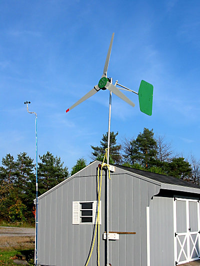
To summarize: I got a cup set from our host, used a tiny 3 phase servo motor as the sensor, put an op amp comparator on one phase to generate a square wave. That's all potted right under the cups and I run three wires for power and signal return up the pole and into the mill shed. In there, it's connected to a little microcontroller that converts the pulses (rpm) into wind speed.


The perspective throws it off a little but the height is within a few inches of the center of the blades; the offset at the top of the pole puts it about three feet away from the blades at their closest approach. BTW: the pole itself is 16 foot "pool cleaning pole" I got at Sam's club for $12 USD.


Haven't seen much wind at all but here's what I've found out so far:


Unloaded, my mill makes about 20 RPMs per MPH of wind. That's pretty much what I expected from entering a TSR 7, 10' diameter blade into Alton's wind calculator. We didn't get enough wind today to see what the MPH/RPM relationship looks like with loaded blades.


Some notes on mill performance:


What I did learn is that the mill blades will spin in a 2 MPH wind although it takes a little over 3 MPH to get them started.


I wish the anemometer had been up this weekend when the front moved through but it wasn't. I did see the mill making 40 to 50 amps for short periods of time; that's way over a kilowatt and pushing 1.5KW. It was the first time that my dump resistors were uncomfortably warm to the touch. (The dump controller was working great; thanks everyone for help with that!)


That's too many watts.


I'd previously added to the tail because the mill was being blown off-wind prematurely (although it was limiting itself nicely to about 33 amps, about 900 watts). I guess that extra tail, a piece of thin plywood clamped on with two c-clamps, added too much weight. I'll want to make a bigger tail and keep the weight about the same but get up on the roof to take the extra tail off while it was fairly calm today.


... am still working on a real tower but not that quickly.


- Ed.

« Last Edit: October 30, 2007, 03:49:11 PM by elt »

scottsAI

  • Hero Member
  • *****
  • Posts: 884
Re: Home-built anemometer project
« Reply #17 on: October 30, 2007, 08:45:43 PM »
Hello Ed,


I found this interesting:

http://www.nrgsystems.com/upload/photos/45AnemometerPerformancePoster.pdf


And:

http://www.cupanemometer.com/technical/The%20Cup%20Anemometer%20History.pdf


Calibration of wind cups.

All wind cups are moving at some slower speed 1/3 to 1/2 of wind speed. The timing or RPM will vary with R distance. I have not taken the time to derive the actual cup speed vs wind speed from the calibration listed in your article.


four pickups and five magnets

Interesting idea, you have no way to identify each magnet, to get angle you must know each magnets location. To understand the variance in speed and direction you must know where the cups are pointing at that time, therefore you must know which magnet is which.


I have not been a big fan of propeller anemometers (pun intended), but looking at this if two propellers were used sin and cos then the magnitude of the wind speed and direction could be calculated! Even simpler, two magnets and two coils! Need propellers rotational direction...


Have fun,

Scott.

« Last Edit: October 30, 2007, 08:45:43 PM by scottsAI »

elt

  • Sr. Member
  • ****
  • Posts: 328
Re: Home-built anemometer project
« Reply #18 on: October 31, 2007, 03:47:24 PM »
This line from the second article caught my attention:


[...] the rotation rate is not constant, even for a constant wind; the rotor "wobbles" in its rotation, as demonstrated quite clearly by Coppin (1982)


I didn't find the Coppin article though I did see it cited in a few others... am wondering if the "wobble" is correlated with the wind direction. If it is, then maybe a "flag" isn't needed to induce one. If not, I'll have to see the magnitude of it to see if it has to masked or can can be ignored.


You wrote:

> I have not taken the time to derive the actual cup speed vs wind speed


I'm more of a picture-guy... I used Figure 7 to get my number because it looked like it had a very high agreement with various anemometers. On second look; however, I see a pretty wide error bar down on the left side where my anemometer is. (My cup set has an 1/R of .125 and plus or minus 20% there shouldn't have been unexpected.)


> you have no way to identify each magnet,


Yes, you're right, it would need an index pulse in order to calibrate.


What I was thinking was that with "n" magnets that the timing variation from the expected 1/n of the rotation period for each pulse would indicate the wind direction without the need for an index pulse and (this I haven't verified) that averaging the input from "m" coils would reduce or cancel the effect of any construction errors without the need for calibration... misplaced components wouldn't effect RPM and I'm thinking that one side you get "position error of misplaced component" plus "function of wind direction" and on the other you "position error of misplaced component" minus "function of wind direction" and with the cosine of 180 being  minus one that it's the component error that falls out... just not sure if there'll be some other minus signs that negate that.


 - Ed.

« Last Edit: October 31, 2007, 03:47:24 PM by elt »

elt

  • Sr. Member
  • ****
  • Posts: 328
Re: Home-built anemometer project
« Reply #19 on: November 01, 2007, 08:47:29 PM »
> [...] would indicate the wind direction without the need for an index pulse


No.


I've modeled it in a spread sheet and it looks like an index pulse is going to be needed... Also, I did find a bazillion reed switches and magnets in the form of left over window and door sensors from my alarm system installation so I ought to be able to make a test bed pretty easily.


 - Ed.

« Last Edit: November 01, 2007, 08:47:29 PM by elt »

scottsAI

  • Hero Member
  • *****
  • Posts: 884
Re: Home-built anemometer project
« Reply #20 on: November 02, 2007, 06:01:37 PM »
Hello Ed,


Let me know when you want to explore this more. Been fun.


I have the weather station working, not installed. Hope to tomorrow.

All the electronics works in a way I can use. Even the broken display, the serial works with the computer, will have to live with defaults which is OK.


Have a good weekend!

Scott.

« Last Edit: November 02, 2007, 06:01:37 PM by scottsAI »