Quite some time ago, I got my hands on a commercial switchmode power supply, 24 volts at 20 amps.
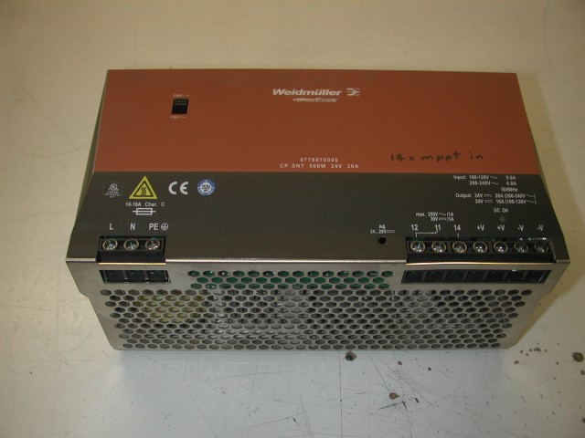
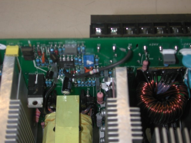
I then proceeded to modify it so the output voltage could be controlled by an external source. I cut one track on the pcb to free up one screw terminal, and hung a resistor from the voltage control op-amp input to this external terminal.
Some figures;
unmodified, the internal adjustment pot gives an output range of 22.44 to 29.17 volts.
setting the internal pot to minimum, and using a bench power supply to drive the new mppt input terminal;
control output
volts volts
- 0 20.85
- 0 27.25
- 0 28.50
This particular power supply probably won't be used much beyond some initial testing. Reason is the input voltage range is too small. Spec sheet says 250-370 volts DC.
However,the latest Soanar catalog landed on my desk last week. They have a similar supply with an input range of 124 to 370 volts dc.
Using a 6U rack panel blank, I then mounted all the bits and wired most of it up.
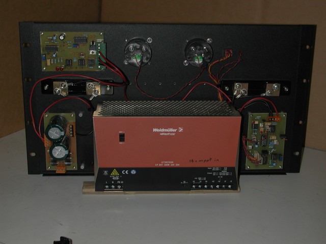
Starting from the bottom left and going clockwise, we have the 3 phase rectifier board; immediately above this is the input current shunt, which feeds the mppt board immediately above it (top right). Top centre are 2 meters, one for rpm and one for output current. Just to the right of these is the star-delta manual over-ride switch with its 2 leds. Bottom right is the metering board, with the output current shunt just above it. There's a row of holes below the meters to mount 4mm banana sockets for test points.
I did do a block wiring diagram in pencil, but it didn't scan too good. I'll do a better one later.
Next weekend I'm gonna put the F&P back in the drill press and start powering this thing for real. After I modify the mppt board so the output control signal is the right polarity to control this psu.
Amanda
